For the last decade or so, we’ve been powering and charging our portable devices with USB. It’s a system that works; you charge batteries with DC, and you don’t want to have a wall wart for every device, so just grab a USB hub and charge your phone and you headphones or what have you. Now, though, we have USB Type C, with Power Delivery. Theoretically, we can pull 100 W over a USB cable. What if we could tap into that with screw terminals?
That’s the idea behind [Jakob]’s entry to the Hackaday Prize. It’s a USB 3.1 Type C to Type A adapter, but it also has the neat little bonus of adding screw terminals. Think of it as jumper cables for your laptop or phone, but don’t actually do that.
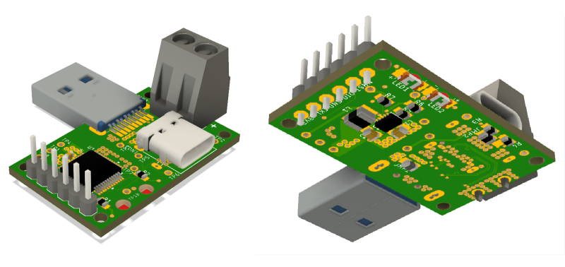
[Jakob]’s board consists of a USB Type C receptacle on one end, and a Type A plug on the other, while in between those two sockets is an STM32G0 microcontroller that handles the power negotiation and PD protocol. This gives the USB Type C port dual role port (DRP) capability, so the power connection can go both ways. Add in a screw terminal, and you can theoretically get 20 V at 5 A through a pair of wires. Have fun with that.
Right now, [Jakob] has all the files in a Gitlab with the schematic and layout available here. It’s an interesting project that has tons of applications of USB hackery, and more than enough power to do some really fun stuff.


I wish they made something similar to this, but with micro B to power a Raspberry Pi from a type C power supplies. Voltage drop across a 5V micro B lead is annoying when trying to power RPis.
You’re in luck, the Raspberry Pi 4 uses USB-C for power instead of micro USB.
Sort-of – it uses a noncompliant implementation that will break with higher-end USB-C products and does not support USB-PD – which is what the person you’re replying to is praising as an advantage.
(Running higher voltages means less resistive losses in the cable)
Yup – yet another RPi design error. Read all about it here:
https://www.scorpia.co.uk/2019/06/28/pi4-not-working-with-some-chargers-or-why-you-need-two-cc-resistors/
Oh well, now they’ve got a quick reason to churn out a RPi4[B] model; then we can all wait forever to actually buy one of those instead!
Both the GitLab and CADLAB links are empty repos.
See dev/hw branch. Not in master.
Files are in git branch https://gitlab.com/jakob.faltisek/usb-type-c-with-pd-upgrade/tree/dev/hw
I just recently purchased a PD Buddy Sink from Tindie for a higher-current project I’ve been working on: https://www.tindie.com/products/clarahobbs/pd-buddy-sink/
I’m excited to see if it fits my need so I can carry a power bank instead of some random battery that doesn’t have another use!
It seems to me like developing a slightly altered variant of an existing OSHW project that is readily available fully assembled on Tindie should not qualify for a HaD Prize.
Especially a Tindie project that is documented in hackaday.io – https://hackaday.io/project/20424-pd-buddy-sink
Since I can’t edit – what WOULD be a great project worthy of a prize is a version of https://www.tindie.com/products/clarahobbs/pd-buddy-wye/ that supported USB 3.0/3.1 data transfer speeds
(USB 3.0 is a lot harder than 2.0 due to the requirement to have orientation detection circuitry and a switch chip to handle orientation changes – The USB 2.0 subset of Type-C was designed to function in an orientation-agnostic way with “dumb” circuitry, while USB 3.0 requires “smart” orientation detection.)
I don’t see any MOSFET on that board rendering capable of switching any useful amount of current. About every week or so any reputable company is announcing the availability of their USB-C PD chips including complete solutions called barrel connector replacement, doing exactly what this kit is supposed to do. Hey, one could even get the schematics for the STM32G071B-DISCO board and simply rip out the relevant parts for PD and create their “own” design to submit to a contest…
The Cypress Data Sheet indicates 900ma max per voltage setting.
or you can just buy one.
https://www.tindie.com/products/clarahobbs/pd-buddy-sink/?utm_source=Hackaday&utm_medium=Banner&utm_campaign=HAD_Tindie_Banners
For a few dollars less, Cypress Semiconductor offer this very similar product with some rather ungainly branding:
https://www.mouser.com/new/cypress-semiconductor/cypress-ez-pd-bcr/
My local electronics supplier came out with a 5.1V power supply specifically for Raspberry Pi’s because of the stupid undervolt issue they suffer from.
I only found out because I went in there to get some parts to build a Micro B to DC Barrel Jack so I could stop this occuring.
They use USB chargers for power supply WITHOUT reading the specs for the range of VUSB under load can drop down to 4.4V. It is a fault of RPi designers to not accommodate this range when you specifically put in a micro USB connector. It costs more confusion than it would have been.
I don’t know who your local electronics supplier is, but chances are that whatever they are selling “specifically for Raspberry Pis” is just a generic high-output USB power supply with slight overvolting for line-loss compensation at high currents. Most are probably sold to people who want their phones to charge at full speed without having to use a stumpy cable.
My local electronics supplier came out with a 5.1V power supply specifically for Raspberry Pi’s because of the stupid undervolt issue they suffer from.
I only found out because I went in there to get some parts to build a Micro B to DC Barrel Jack so I could stop this occuring.
Report comment
Reply
I have few powerbanks that can output 4.5-12.5V in steps of 0.5V. But they’re not PD or QC compatible. I’d like to see QC/PD compatible powerbank that also has option of manually setting voltage on separate output (barel connector preferably). That would make powerbank pretty universal and versatile for powering bunch of electronics you can’t power with USB.
Sound like we re back to the age of power bricks with adjustable voltages minus the ”Universal” plug set. Let’s hope this time the voltage is regulated and more accurate. The old design just have a multiple tab transformer with a rectifier and cap.
Very confused at this stage. The article says extracting power from type C, but the README.md says converting a Type-A to a Type-C? In other words injecting power into Type-C and using the data lines from the Type-A drive the Type-C.
I’m not sure I’d call this DRP capability. I don’t see a way to actually prescribe a voltage to deliver. This looks like a great way to brick devices by putting 20V into those screw terminals on a device that only asks to receive 5V.
Mounting hole fail again. No room for proper mounting hardware. Do people even check this stuff? Come on, just go the extra mile….
I would love to see any USB cord pull 5 amps!!! Majority of the USB cords are crap!
If I’m not mistaken even with a lousy cable these quick chargers can still work well. I think they do 5V load-end two-wire voltage sensing (e.g. a Kelvin type Hi-Z bridge), then the charge controller chip increases the source voltage well above 5V to overcome the I*R voltage drop of the lousy cable resistance. Yeah at some point the cable might heat up or burn, but I’m pretty sure the charge controller won’t let that happen. So if you use something like six ft. (2m) cheap cable with one of these quick chargers you may not see a full 5A, but it may get close.