The sort of pumps used in the filtration systems of fountains and swimming pools don’t take kindly to running dry. So putting such a pump on a simple timer to run while you’re away comes with a certain level of risk: if the pump runs out of water while you’re gone, you might come home to a melted mess. One possible solution is a float sensor to detect the water level in whatever you’re trying to pump, but that can get complicated when you’re talking about something as large as a pool.
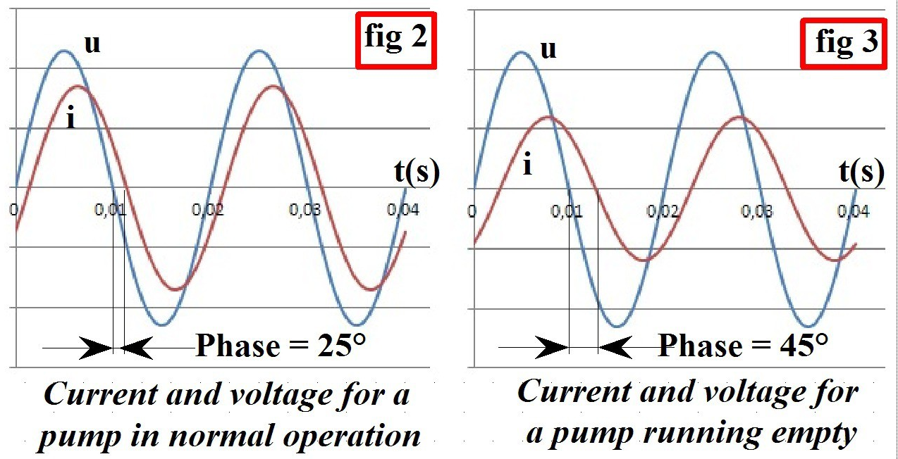 For his entry into the 2019 Hackaday Prize, [Luc Brun] is working on controller that can detect when the pump is running dry by monitoring the phase shift between voltage and current. With an inductive load like a pump, the current should lag behind the AC voltage a bit under normal operation. But if they become too far out of phase with each other, that’s a sign that the pump is running in a no-load condition because there’s no water to slow it down.
As [Luc] explains in the project write-up, simply monitoring the pump’s peak current could work, but it would be less reliable. The problem is that different motors have different current consumptions, so unless you calibrated the controller to the specific load it’s protecting, you could get false readings. But the relationship between current and voltage should remain fairly consistent between different motors.
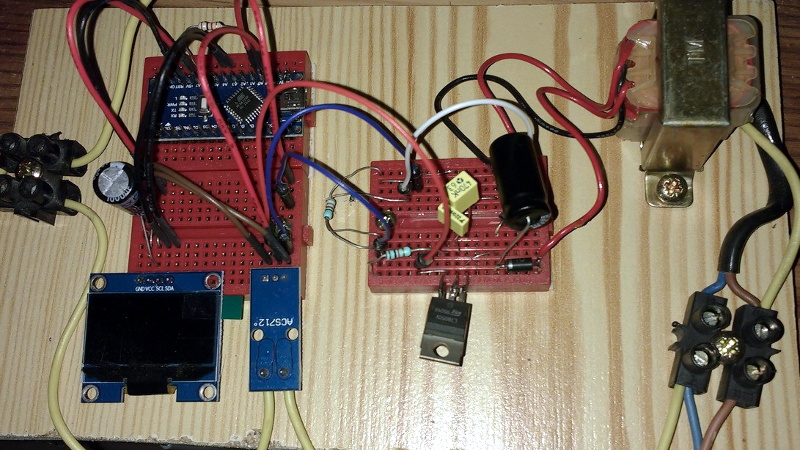
The controller is powered by a Arduino Nano and uses a ACS712 current sensor to take phase measurements. Since he had the ability to toggle the pump on and off with a relay attached to the Arduino, [Luc] decided to add in a few other features. The addition of a DS1307 Real Time Clock means the pump can be run on a schedule, and an HC-05 Bluetooth module lets him monitor the whole system from his smartphone with an Android application he developed.
Since the theme of this year’s Hackaday Prize is designing a product rather than a one-off build, judges will be looking for exactly the sort of forward thinking that [Luc] has demonstrated here. As the controller is currently a mass of individual modules held inside a waterproof enclosure, the next steps for this project will likely be the finalization of the hardware design and the production of a custom PCB.


Really clever idea. Wonder if something similar is/could be implemented in industrial applications.
Yes, used in industrial applications for exactly this application. Example: http://www.lovatoelectric.com/selectProduct.aspx?id=410015&text=Pump-protection-relays
In India the unit is already in market since 15 years. And give dry running and overload protection for upto 5 hp pump.
I like this. Could the same mechanism be used to detect when the pump is overloaded? Like it happened with me when the selenoids fail to open and the pump was just running until the plastic elbow melted and gave way.
Put a temperature sensor on the motor so it would detect overheating for any reason.
A lot of the asychronous motors of the more expensive types have a thermistor fitted in the windings , already,pool pumps are generally little single phase or star wound types of a lower economic value so perhaps that is why some don’t have it.
Wouldn’t simply measuring the RMS current be enough to detect the load?
I know they’re measuring the phase shift to get the real power, but this is a very simple system and you don’t need all that.
>”the relationship between current and voltage should remain fairly consistent between different motors”
Nope. It depends on the power of the motors. It works consistently for motors larger than about half a kilowatt, but for smaller motors, especially for very small motors the size of aquarium pumps(10-50W), the effect is dominated by the resistance of the motor coils rather than its reactance and you still have to calibrate.
If the pump is a non-positive displacement direct drive ,then ,if the shaft snaps or the coupling breaks then the same phase shift will be observed, which is usually tripped by the rise in current during those events,by an overload relay.Your model may give false positives when the pool is still full ,but the mechanics are shot , a shaft spinning in coupling might give similar results ,perhaps the quantification of the phase shift in empirical modelling might be the next step.
Just thinking aloud!
I’d call this a feature, not a bug. As a safety monitoring device, any unexpected unloading is cause for concern.
The unloading can occur after catastrophic failure, if it is detected after the pump has snapped its shaft it is not such a helpful feature, if it does not provide redundancy in terms of plant protection.In most pump circuits there are a series of safety features wired ;a common one is the low pressure cut -out ,some have differential,pressure switches as well.
There is already a relay for that! From ABB, it’s called a Motor Load Monitoring Relay – CM-LWN.
TIL
Thanks for letting me know about that rabbit hole. Very neat devices that i never knew existed.
If you could incorporate this with a timer and Bluetooth it will sell. Look at pentair or jandy
I wonder whether the Sonoff POW hardware is capable of the required measurements needed to support this approach?
Would this principle of how the current lags behind the voltage with differing phase shifts dependent on the load on the pump also apply to elctric motors in general? Can that typically be used to measure the load on any motor (including small ones), so long as it is either an AC motor or a motor running on pulses of DC and not a DC motor running fromma constant voltage.
Wouldn’t a flow or pressure switch on the pump outlet also do the same job in a much simpler way?
Instead of just measurering phase shift it seems more logical (and robust) to use a RMS power measurement chip, which uses both power and phase shift to monitor the load of the pump.