[Ben Eater] is back with the second part of his video series on building a simple video card that can output 200×600 pixels to a display with nothing but a VGA connection, a handful of 74-logic chips and a 10 MHz crystal. In this installment we see how he uses nothing but an EEPROM and a handful of resistors to get an image onto the screen.
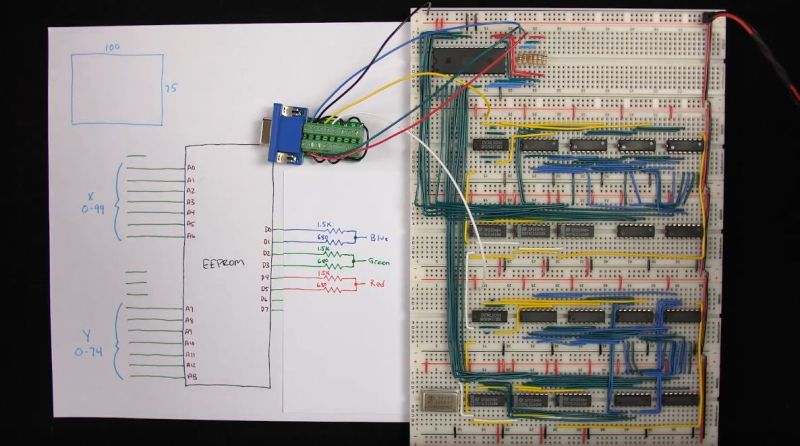
The interesting part is in how the image data is encoded into the EEPROM, since it has to be addressable by the same timing circuit as what is being used for the horizontal and vertical timing. By selecting the relevant inputs that’d make a valid address, and by doubling the size of each pixel a few times, a 100 x 75 pixel image can be encoded into the EEPROM and directly addressed using this timing circuit.
The output from the EEPROM itself not fed directly into the monitor, as the VGA interface expects a 0 V to 0.7 V signal on each RGB pin, indicating the brightness. To get more than three colors out of this setup, [Ben] builds up a simple 2-bit DAC that allows for two bits per channel, meaning four brightness levels per color channel or 64 colors effectively.
See the video after the link for the full details. While pretty close to perfect, a small issue remains at the end in the forms of black vertical lines. These are caused by a timing issue in the circuit, with comments on the YouTube video suggesting various other potential fixes. Have you breadboarded your own version yet to debug this issue before [Ben]’s next video comes out?


I had a similar issue with the lines on my own VGA circuit which is simply fixed by adding a latch to the output and clocking it with the pixel clock. Even if the rom were fast enough or he was using fast SRAM (like me) the memory is not synchonous so needs to be made so by registering it with a latch
Awesome work and incredibly informative.
I thought we had moved passed using that particular image… Sigh.
If you mean Lenna, you didn’t watch the video, Ben Eater sends a tropical bird as the test image.
It’s in the thumbnail… Clickbait it seems, which actually makes it worse.
Why would we? It’s liberally licensed and is pretty much the de facto reference for image processing.
It’d be like moving past “hello world”.
This guy’s content is 10/10.
The part count could be greatly reduced by having the EEPROM’s left over 2 bits generate the h-sync and v-sync signal.
All you need then is a total-image-size limit comparator.
Which you can also eliminate by having a special code in the EEPROM reset the counter such as (Vsync bit ANDed with Red bit 0 ) -> counter reset (The color should be always be 0 during blank)
Benchhof featured the same project two weeks ago. https://hackaday.com/2019/07/07/low-res-video-card-is-still-amazing-since-its-made-out-of-logic-chips/
It all doesn’t need to be that complex either. Also the control signal for the counters can come from the pixel memory. Hackaday featured that two years ago: https://hackaday.com/2017/03/07/vga-without-a-microcontroller/
A possible change is to use 3 bits for R and G, and 2 for B, taking advantage of the human eye being less sensitive to blue than red/green.
I doubt the DAC he has works as well as theory because he just assumed the bits turned off were tri stated, which they are not. So in either of the cases of having one pin on and the other off, the voltage divider has another leg returning back to the low output on the eprom. I would have used 3 eproms and 3 8 bit dac’s to output 24 bit color but it was cool he was able to do what he did with real simple analog stuff.
All that being said, it was cool that he was able to do what he did with the stuff he had to do it with. I am pretty sure I would not bother working at that low a level, but it was fun watching it come together.
Many decades ago a friend of mine made R 2R dac’s out of resistors and fit them along with a female RCA jack into the shell of a DB25 connector you could plug into a printer port and wrote a little program to let you play sound files through it. He used to sell them along with disks of sound files at computer shows. He was a clever pup and designed a real clever little box to package them in. They looked like a real product, not something assembled on the kitchen table…..
Keep up the great work, Ben :) Great stuff!
I know the point of this project is “minimal viable hardware to output VGA images from ROM” but it galls me slightly that the resolution is a quarter of what it could have been for the want of one address line. Two of the same EEPROM chip and one pin used for bank switching could rectify that and give us the 200×150 which his original clock calculations arrived at. Also the two-bit DAC is a nice simple example but given an 8-bit ROM it would have been nice to see how well it could do with 3-3-2 bit colour depth.
I don’t know if this is really “minimal viable hardware”. There are several projects doing VGA output with real time visual effects etc. on just an AVR with no extra hardware.
This seems like an incredible amount of extra circuitry. This guy has stable VGA output (next to a lot of CPU cycles used for his effects and audio) from just an Atmega88 without any peripheral chips what so ever: http://linusakesson.net/scene/craft/index.php
The Atmega88 is far more complex than this circuit. It just happens to be shrunk down and all on one chip. Lower chip count does not necessarily equate to less complexity.
While not a TTL implementation or TVT, the microcontroller VGA circuits do expose some neat tricks. The 1st gen Parallax Propeller does a VGA display and there are numerous VGA or N x 3.579MHz TVT microcontroller and logic (discrete, CPLD, & FPGA) projects. It’s so satisfying to build and debug a project where you literally see the output regardless of which technology you use.