We’ve all seen them, the rotary tools that look almost, but not quite exactly, like a Dremel. They cost just a fraction of the real thing, and even use the same bits as the official Bosch-owned version. At first glance, they might seem like a perfect solution for the hacker who’s trying to kit out their workshop on a tight budget. There’s only one problem: the similarities between the two are only skin deep.

As [Vitaly Puzrin] explains, one of the big problems with these clones are the simplistic electronics which have a tendency to stall out the motor at low RPM. So he’s developed a drop-in replacement speed controller for his particular Dremel clone that solves this problem. While the module design probably won’t work on every clone out there in its current form, he feels confident that with help from the community it could be adapted to other models.
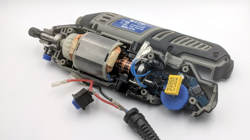
Of course, the first step to replacing the speed controller in your not-a-Dremel is removing the crusty old one. But before you chuck it, you’ll need to recover a few key components. Specifically the potentiometer, filter capacitor, and the motor terminals. You could possibly source the latter components from the parts bin, but the potentiometer is likely going to be designed to match the tool so you’ll want that at least.
The microprocessor controlled upgrade board uses back EMF to detect the motor’s current speed without the need for any additional sensors; important for a retrofit module like this. [Vitaly] says that conceptually this should work on any AC brushed motor, and the source code for the firmware is open if you need to make any tweaks. But hacker beware, the current version of the PCB doesn’t have any AC isolation; you’ll need to take special care if you want to hook it up to your computer’s USB port.
On the other hand, if you’re willing to buy a cheap rotary tool just to crack it open and replace the electronics, you might as well just build your own. If you’re feeling particularly adventurous, you can always abandon the electric motor and spin it up with a tiny turbine.


I have a original Dremel Model 3000 (pretty basic), and behave like the original version of the clone in the video. Waste of money for the real thing? And mine is not even stable at very low RPM with no load.
Are you shure that you got the real thing?
I just bought a Dremel 3000 including the flexshaft and it definitely does not stall at low RPM.
Basically the indications are RPM with no load. With low ones, the torque is very low. It was bought from a big chain of tools, official seller of Dremel and Bosch too. Maybe I’m not using it correctly.
I have a really old (bought about 1980) Dremel model 380-5. It does not come close to stalling at low speed. It’s also held up well, about 40 years of medium to light use (depending on what I was working on at different periods) and it still works perfectly.
Mhmm. I just looked on YouTube for videos of my model, when they use it against a surface the speed goes down significantly. It cannot adjust the torque. If I use it at 200rpm, is pretty weak (and not sure what the function of that). Above 3k RPM is pretty ok. Is it your keeping a sensible torque below 1000rpm?
But isn’t that a corded Dremel? That’s not comparable.
I have a Dremel tool that I bought years ago. Every time I use it it scares me. They are so big and difficult to hold and control, I wonder how many trips to the ER they cause every year.
At work, and soon at home, I have a dental lab handpiece with all sorts of nifty tungsten carbide cutters and polishing doo-dads. It is small enough to be easily hand held and controlled to do detailed work, has lots of torque, runs up to 50k rpm and most unlike a Dremel tool, it is quiet! They are available with brush and brushless motors. Both work well, but sooner or later you’ll have to replace brushes if you get that type. The bits for it are very inexpensive.
If you ever try a dental lab handpiece, you’ll never go back to a Dremel.
Any recommendations on what to look for as far as brands and such goes?
I went the other way.. Found the Dremel(One of the original muiltitool series, 240v version) to be underpowerd except for small jobs like cutting plasterboard or reshaping holes in plastic cases, ended up going for a long nose 900W die grinder.
8mm shaft carbide burr bits really do a nice job at getting stuff done.
is there a 110V version of the Hilda 180W (knockoff of a knockoff or otherwise)? 220V is useless with my inferior North American grid power. all the 110V dremels on ebay that I looked at have a different case….
I upgraded from a Dremel to a Proxxon last year. Quite a difference in quality between the two. The reduction of noise alone is worth the upgrade.
I wonder if the Hilda people will take this design and incorporate it into their products? :P
How can the schematics (on EasyEDA) be read by anyone except the creator.
Worse than those made in Eagle, all the time designators over the parts symbols.
No nets , connection from starting point to end point.
No, no.
Your welcome to clone it and fix it :) EasyEDA encourages that.
As a hackerspace person, you get to see happy little hackers who learn enough to do something… and thats it. If it works, its finished. Personally I NEED nets to understand my own schematics ;)
I’m glad he released it there for everyone to build on. I think we have one of those not-so-dremel’s that needs an upgrade :D
Hi,
sure I could take some effort in to make it understandable.
But this could be done by the maker in first place.
Regarding the usability the drawing is pretty much worthless.
The reader has to put in a lot og Grips-work to understand how it works.
This is what a schamatics should tell by design.
With lines from starting to endpoint i ean they should not be arrows with names, nets should be drawn from start to end, they could be simplified if there is few space only , with a sing line and a number that tells how many lines are included.
This sheet is almost empty. All lines could be drawn completely.
I can tell you from my professional work I had serviced complex systems much much larger than this piece of … .
The documentation had all the wires drawn, went over many pages per book and it was EASY to work with.
So I CAN tell how it could be made. But the maker told, they have had no time to do it better.
If you would look at my makes on some sites you would see I put some effort in to let the poeple easily understand and redo what I have made.
Salute.
If you can’t read the simple schematic for this project (https://image.easyeda.com/histories/d5cbe3d753cb4377a84944b36f362451.png) you probably shouldn’t be allowed near a soldering iron. Connecting all of the named nets would just make the whole schematic messier and obscure the logical distinction between the different circuit blocks (power supply, line sync generator, motor driver, and microprocessor to connect them all). It could benefit from some names around the blocks but really with such a simple design it is not necessary IMHO
The schematic is not bad. Often I prefer to see more connections in the schematic, like drawing the microcontroller in the center and arranging the parts around. Especially small function groups which consist of just a few components.
Of course it does not make sense to draw all connections across the sheet. Labels are a useful thing. Bad example: Once I saw just a single resistor with labels on both ends. I did not like that.
In the end it is a question of personal preferences.
You seem unreasonably angry about this. Did he sleep with your wife or something?
No, I just have had to read a lot of spaghetti schematics in my life!
For those who are happy with trash and crap, not paying respect to the user,
Look at this guy.
His name Markus,
his make: the RepRap Generation7 cnc controller board.
Follow the links, read on, get the experience of how to get a well designed bunch of product, documentation, service.
http://reprap-diy.com/ (shop site)
https://reprap.org/wiki/Generation_7_Electronics
https://github.com/Traumflug/Generation_7_Electronics/tree/ExtensionBoard-USB-B-1.0
I’m a happy user of this kit, self assembled several years ago.
Cheers
After I burned out my second Dremel I decided never to buy a Dremel again. I use the fake ones now and they work better! Not a single burned out machine yet.
Dremel is crap imo.
And these tools are meant for high RPM so it quite normal that it doesn’t work at low speeds.
Dremel. Pfff. Trash. They might have started as an A brand, but especially their accessories are mediocre to say the least. I wanted a drill press stand to drill pcb holes. The dremel version costed around 80 euro and my drill moved at least 2mm sideways going down because of all the plastics used in the “construction” of the thing. Now i use A Proxxon with a cheaper and all metal drill press. For me this writeup can be compressed in one sentence: the more you run over a dead cat, the flatter it gets (as quoted from the talking moose macintosh desk accessory from 1989)
Some comments on the schematic:
The PSU is overly complicated. If you use a linear post-regulator anyway, the optocoupler feedback is not necessary, direct feedback would be precise enough. Probably also without the linear regulator.
The diodes D4 and the 1,5k resistor in the line frequency sensing are not necessary. PB1 is not 5V tolerant, so it can take +/-5 mA of injection current into the protection diodes. With your 300k resistance the peak current at 315Vpk is just slightly above 1mA. And you get faster edges for the phase sensing (better precision)
But I can not see any beck EMF tracking or measurement. I see only a current sense amplifier.
Look at AC->PRB_PWR voltage divider block for back-EMF measurement ;)
Kudos to [Vitaly] for really nice project. I made the same thing 10 years ago with ATmega8 :)
My bad, here it’s not straighforward as I thought. Found the description here: https://github.com/speedcontrols/ac_sc_grinder/tree/master/doc
If you’re considering buying a rotary tool – especially a name brand – you owe it to yourself to try out a Foredom-style flex-shaft tool. You can get cheap chinese ones (that still have “Foredom” cast into the motor housing) for under $100. There’s one on Banggood for $84 right now.
I resisted for decades, but I wish I jumped sooner. The control and power are so much better. You’re not fighting the gyroscopic action of the motor, and you have proper torque.
Way worth spending the little bit extra over the $50-something dollars you’ll be into a Hilda tool after mods.
linky link? Purdy pleez?
What’s the difference between the 4mm and 6mm versions? Is that the diameter of the flex shaft? The max size of the bit it will hold? I can’t seem to find anything that says…
Should be this one: https://www.banggood.com/-p-960103.html
Well, that’s 220v, so not a lot of use to me, but thanks anyway.
Would it be nice to have something that does not require a degree, any kind of online editor.
Just put a png oder pdf file there, with al signal trces pleas.
At least for those poeple who are kind of old school not willing to learn a new schematic editor.
Taken from the past project iles melody gong powered by Z80/U880 MCU.
Dead easy, everybody can understand EASiLY.
Schematic with bus/net, pcb copper side, top side with parts.
https://abload.de/image.php?img=z80_u880_gong_slp2ijc6.jpg
https://abload.de/image.php?img=z80_gong_top4qkmz.png
https://abload.de/image.php?img=z80-u880_gong_bottomvgj4f.png
If you need support,ask the man who modified the schematics first published in 1984 by the GdR radio amateur magazin “Funkamateur”
email:dg1afg@ov-w38.de
Apologies for this tangent. I found this site while doing a search to try to identify an 8 pin chip labeled “NB2056” with the second line reading “0807K” (which I’m guessing is a date code) on the speed ctrl board of an el-cheapo 9.6volt rotary tool (other parts include a unidirectionally fried mosfet and some caps and resistors). I’m guessing the chip might just be a 555 variant, but in case its an interesting variant or something else, and still good (but possibly differently enough spec’d that randomly applying current to it might possibly kill it), I’m hoping to get some actual data before taking the risk, just in case it’s something better. Does anyone recognize the nomenclature? Googling has led nowhere useful.
I own a HERSO rotary tool that stoped working, it has that exact speed control circuit in the image, can seem to find that replacement part anywere, what is the most common component that fails in this circuit? is it the potentiometer?… maybe if I could swap the pot for your every day panel-mount one
Dermel history as I know it. The first tools had a series wound universal brushed motor. They tend to rev high with no load and bog down the most under load noisy, and at low speeds awful.
80’s era they used a permanent magnet motor with a simple electronic speed control, full face knob on the side (not thumbwheel), and cylindrical shaped sides not tapered throughout. These had constant RPM under load all the way down to 10% and are the best.
Later models went back to series wound crap with zingy brush holders to boot. I have a Black and Decker 18 volt PM tool which on a regulated bench supply gives constant RPM. No reason to go to high voltage the wires are so thin and the insulation is more critical. 220V and such fine wire no thanks.