Gesture Controlled Doom

DOOM will forever be remembered as one of the founding games of the entire FPS genre. It also stands as a game which has long been a fertile ground for hackers and modders. [Nick Bild] decided to bring gesture control to iD’s classic shooter, courtesy of machine learning.

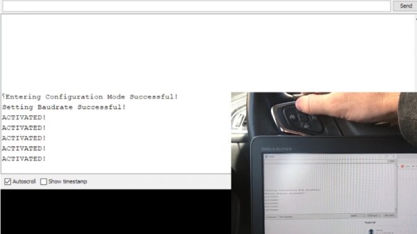
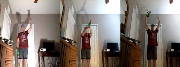
The setup consists of a Jetson Nano fitted with a camera, which films the player and uses a convolutional neural network to recognise the player’s various gestures. Once recognised, an API request is sent to a laptop playing Doom which simulates the relevant keystrokes. The laptop is hooked up to a projector, creating a large screen which allows the wildly gesturing player to more easily follow the action.

The neural network was trained on 3300 images – 300 per gesture. [Nick] found that using a larger data set actually performed less well, as he became less diligent in reliably performing the gestures. This demonstrates that quality matters in training networks, as well as quantity.

Reports are that the network is fairly reliable, and it appears to work quite well. Unfortunately, playability is limited as it’s not possible to gesture for more than one key at once. Overall though, it serves as a tidy example of how to do gesture recognition with CNNs.

If you’re not convinced by this demonstration, you might be interested to learn that neural networks can also be used to name tomatoes. If you don’t want to roll your own pose detection, check out this selfie drone that uses CMU’s OpenPose library. Video after the break.

Continue reading “Gesture Controlled Doom”

High Precision Analog IO With Digital Pins

Reading the temperature of your environment is pretty easy right? A quick search suggests the utterly ubiquitous DHT11, which speaks a well documented protocol and has libraries for every conceivable microcontroller and platform. Plug that into your Arduino and boom, temperature (and humidity!) readings. But the simple solution doesn’t hit every need, sometimes things need to get more esoteric.

The technique summarized by an image from Microchip Appnote AN685

For years we’ve been watching [Edward]’s heroic efforts to build accessible underwater sensing hardware. When we last heard from him he was working on improving the accuracy of his Arduino’s measurements of the humble NTC thermistor. Now the goal is the same but he has an even more surprising plan, throw the ADC out entirely and sample an analog thermistor using digital IO. It’s actually a pretty simple trick based on an intuitive observation, that microcontrollers are better at measuring time than voltage. 

The basic circuit

The circuit has a minimum of four components: a reference resistor, the thermistor, and a small capacitor with discharge resistor. To sense you configure a timer to count, and an edge interrupt to capture the value in the timer when its input toggles. One sensing cycle consists of discharging the cap through the discharge resistor, enabling the timer and interrupt, then charging it through the value to measure. The value captured from the timer will be correlated to how long it took the cap to charge above the logic-high threshold when the interrupt triggers. By comparing the time to charge through the reference against the time to charge through the thermistor you can calculate their relative resistance. And by performing a few calibration cycles at different temperatures ([Edward] suggests at least 10 degrees apart) you can anchor the measurement system to real temperature.

For all the gory details, including tips for how to save every last joule of energy, check out [Edward]’s post and the Microchip appnote AN685 he references. Besides this series [Edward]’s Cave Pearl Project has already yielded an impressive number of Hackday posts. For more great hardware writeups check out a general hardware build for a single sensing node, or the “temperature sensor” [Edward] made with no external parts at all!

Make Your Own SPL DB Meter With A Microphone And MCU

Measuring equipment such as SPL (Sound Pressure Level) decibel meters may seem daunting, but this article by [Shawon M. Shahryiar] shows that making your own need only have two essential ingredients: a microphone and a microcontroller. Obviously the microphone is for measuring the sound pressure level, and its output is then fed into the ADC of the microcontroller which does some math before sending the result to a display.

[Shawon] runs through all of the theory behind the calculations that have to be performed, before showing the C code that runs on the PIC18F242 8-bit MCU targeted by the prototype setup. The display is a graphical LCD type, capable of displaying the text with values as well as bar graphs indicating the measured levels. For the measurements themselves, the RMS value is taken of 16 ADC samples while the algorithm takes into account the specifications of the Seeed-sourced microphone module, specifically its average 50 dB sensitivity rating.

Although a full schematic is not provided, the essentials are all there for anyone to build their own SPL dB meter using virtually any microphone and MCU with built-in ADC. As the article also notes, opting for a higher quality microphone will yield better result and of course a faster MCU will offer more options, including FFT processing. Since the code itself is fairly basic, it should be easy enough to port it to an ARM-based MCU, which would allow one to use for example a TFT LCD.

Take a peek after the break for a video of the article’s SPL dB meter in action.

Continue reading “Make Your Own SPL DB Meter With A Microphone And MCU”

Developing An Automatic Tool For CAN Bus Hacking

In the old days, a physical button or switch on the dashboard of your car would have been wired to whatever device it was controlling. There was potentially a relay in the mix, but still, it wasn’t too hard to follow wires through the harness and figure out where they were going. But today, that concept is increasingly becoming a quaint memory.

Assuming your modern car even has physical buttons, pushing one of them likely sends a message over the CAN bus that the recipient device will (hopefully) respond to. Knowing how intimidating this can be to work with, [TJ Bruno] has been working on some software that promises to make working with CAN bus user interfaces faster and easier. Ultimately, he hopes that his tool will allow users to rapidly integrate custom hardware into their vehicle without having to drill a hole in the dashboard for a physical control.

But if you’re the kind of person who doesn’t like to have things done for them (a safe bet, since you’re reading Hackaday), don’t worry. [TJ] starts off his write-up with an overview of how you can read and parse CAN messages on the Arduino with the MCP2515 chip. He breaks his sample Sketch down line by line explaining how it all works so that even if you’ve never touched an Arduino before, you should be able to get the gist of what’s going on.

As it turns out, reading messages on the CAN bus and acting on them is fairly straightforward. The tricky part is figuring out what you’re looking for. That’s where the code [TJ] is working on comes in. Rather than having to manually examine all the messages passing through the network and trying to ascertain what they correspond to, his program listens while the user repeatedly presses the button they want to identify. With enough samples, the code can home in on the proper CAN ID automatically.

The upside to all this is that you can activate aftermarket functions or hardware with your vehicle’s existing controls. Need an example? Check out the forward-looking camera that [TJ] added to his his 2017 Chevy Cruze using the same techniques.

Continue reading “Developing An Automatic Tool For CAN Bus Hacking”

A Drop-In Upgrade Module For Cheap Rotary Tools

We’ve all seen them, the rotary tools that look almost, but not quite exactly, like a Dremel. They cost just a fraction of the real thing, and even use the same bits as the official Bosch-owned version. At first glance, they might seem like a perfect solution for the hacker who’s trying to kit out their workshop on a tight budget. There’s only one problem: the similarities between the two are only skin deep.

Recovering components from the original controller

As [Vitaly Puzrin] explains, one of the big problems with these clones are the simplistic electronics which have a tendency to stall out the motor at low RPM. So he’s developed a drop-in replacement speed controller for his particular Dremel clone that solves this problem. While the module design probably won’t work on every clone out there in its current form, he feels confident that with help from the community it could be adapted to other models.

Of course, the first step to replacing the speed controller in your not-a-Dremel is removing the crusty old one. But before you chuck it, you’ll need to recover a few key components. Specifically the potentiometer, filter capacitor, and the motor terminals. You could possibly source the latter components from the parts bin, but the potentiometer is likely going to be designed to match the tool so you’ll want that at least.

The microprocessor controlled upgrade board uses back EMF to detect the motor’s current speed without the need for any additional sensors; important for a retrofit module like this. [Vitaly] says that conceptually this should work on any AC brushed motor, and the source code for the firmware is open if you need to make any tweaks. But hacker beware, the current version of the PCB doesn’t have any AC isolation; you’ll need to take special care if you want to hook it up to your computer’s USB port.

On the other hand, if you’re willing to buy a cheap rotary tool just to crack it open and replace the electronics, you might as well just build your own. If you’re feeling particularly adventurous, you can always abandon the electric motor and spin it up with a tiny turbine. Continue reading “A Drop-In Upgrade Module For Cheap Rotary Tools”

The South American Power Outage That Plunged 48 Million Into Blackout

A massive power outage in South America last month left most of Argentina, Uruguay, and Paraguay in the dark and may also have impacted small portions of Chile and Brazil. It’s estimated that 48 million people were affected and as of this writing there has still been no official explanation of how a blackout of this magnitude occurred.

While blackouts of some form or another are virtually guaranteed on any power grid, whether it’s from weather events, accidental damage to power lines and equipment, lightning, or equipment malfunctioning, every grid will eventually see small outages from time to time. The scope of this one, however, was much larger than it should have been, but isn’t completely out of the realm of possibility for systems that are this complex.

Initial reports on June 17th cite vague, nondescript possible causes but seem to focus on transmission lines connecting population centers with the hydroelectric power plant at Yacyretá Dam on the border of Argentina and Paraguay, as well as some ongoing issues with the power grid itself. Problems with the transmission line system caused this power generation facility to become separated from the rest of the grid, which seems to have cascaded to a massive power failure. One positive note was that the power was restored in less than a day, suggesting at least that the cause of the blackout was not physical damage to the grid. (Presumably major physical damage would take longer to repair.) Officials also downplayed the possibility of cyber attack, which is in line with the short length of time that the blackout lasted as well, although not completely out of the realm of possibility.

This incident is exceptionally interesting from a technical point-of-view as well. Once we rule out physical damage and cyber attack, what remains is a complete failure of the grid’s largely automatic protective system. This automation can be a force for good, where grid outages can be restored quickly in most cases, but it can also be a weakness when the automation is poorly understood, implemented, or maintained. A closer look at some protective devices and strategies is warranted, and will give us greater insight into this problem and grid issues in general. Join me after the break for a look at some of the grid equipment that is involved in this system.

Continue reading “The South American Power Outage That Plunged 48 Million Into Blackout”

Crowd Supply Hack Chat With Josh Lifton

Join us on Wednesday, July 24th at noon Pacific for the Crowd Supply Hack Chat with Josh Lifton!

When you’re ready to take your Next Big Idea from a project to a product, you face problems that don’t normally present themselves to the hobbyist. Building one of something is quite different from building many of them, and soon you’re dealing with issues with parts suppliers, PCB fabrication, assembly, packaging, shipping, marketing, and support.

It takes a lot to get your idea to market, and a guiding hand would be most welcome to the budding hardware tycoon. That’s the logic behind Crowd Supply, the Portland-based crowdfunding and mentoring company. Josh Lifton is its CEO, and he’ll drop by the Hack Chat to answer all your questions about how crowdfunding works, what Crowd Supply offers to help creators, and what the fundamentals of a successful project are.

join-hack-chatOur Hack Chats are live community events in the Hackaday.io Hack Chat group messaging. This week we’ll be sitting down on Wednesday July 24 at 12:00 PM Pacific time. If time zones have got you down, we have a handy time zone converter.

Click that speech bubble to the right, and you’ll be taken directly to the Hack Chat group on Hackaday.io. You don’t have to wait until Wednesday; join whenever you want and you can see what the community is talking about.

[Photo credit: Jon House, Portland Tribune]