Many people assumed the smartphone revolution would kill the dedicated handheld game system, and really, it’s not hard to see why. What’s the point of buying the latest Nintendo or Sony handheld when the phone you’re already carrying around with you is capable of high-definition 3D graphics and online connectivity? Software developers got the hint quickly, and as predicted, mobile gaming has absolutely exploded over the last few years.
 But at the same time, we’ve noticed something of a return to the simplistic handheld systems of yore. Perhaps it’s little more than nostalgia, but small bare-bones systems like the one [Mislav Breka] has entered into the 2019 Hackaday Prize show that not everyone is satisfied with the direction modern gaming has gone in. His system is specifically designed as an experiment to build the most minimal gaming system possible.
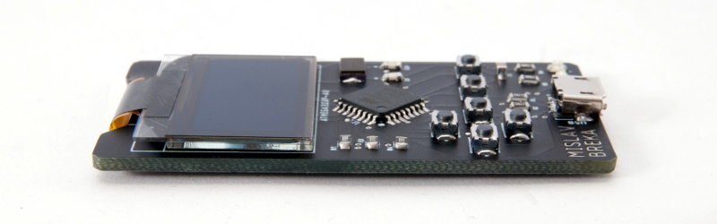
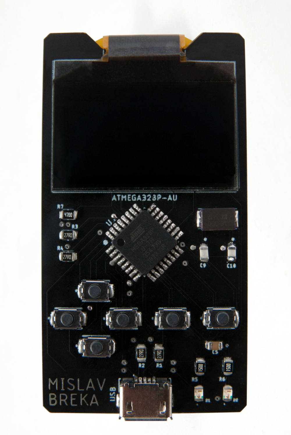
In terms of the overall design, this ATMega328 powered system is similar to a scaled-down Arduboy. But while the visual similarities are obvious, the BOM that [Mislav] has provided seems to indicate a considerably more spartan device. Currently there doesn’t seem to be any provision for audio, nor is there a battery and the associated circuitry to charge it. As promised, there’s little here other than the bare essentials.
Unfortunately, the project is off to something of a rocky start. As [Mislav] explains in his writeup on Hackaday.io, there’s a mistake somewhere in either the board design or the component selection that’s keeping the device from accepting a firmware. He won’t have the equipment to debug the device until he returns to school, and is actively looking for volunteers who might be interested in helping him get the kinks worked out on the design.


A bit difficult to help without schematics, if he posted those I’m sure someone would give him a fix almost immediately.
Bingo, and there’s the magic silver bullet right there. If you need help you have to make it easy for others to help you. This means posting as much info about your problem as possible. I cant tell you how many forum posts I’ve seen where someone asks how to fix a specific bug their program has but forgot/didn’t want to post the actual code lol.
The forum posts that I really hate is where there is a description of the problem, and it matches what you’ve been searching for for days, only to find a second post that simply says “Nevermind, fixed it”.
Oh God yes. This applies to everything.
Lol those are definitely the worst
https://xkcd.com/979/ seems wholly relevant here.
As for the article: most of the issues I’ve seen with programming are either because the reset pin lacks a pullup resistor (so it programs but doesn’t run) or the more obvious ISP connection problems. A possibility would be soldering solid core wire to the correct pins on an unmounted 328, programming it, then soldering it to the board, to decide that it’s a board problem or a chip/programmer problem.
Atmega ISP doesn’t require any external components – not even the pull up on /Reset pin.
That truly must be annoying.
Maybe one should actually post one’s solution, just in case?
(if one desires to be nice and knows that no one else has asked about it before. After all, one would likely have searched around for a while oneself as well.)
I hate those!
I made a post in a hurry. I will add schematics and back-side photos as soon as I get access to my PC no worries.
Hi, I made that post in a hurry as I was on vacation. I just added schematics to this project, so you can check it out if you’re still interested. Thank you!
Love the idea and how small the board is. I’ve sketched out a similar thing, only using an LED matrix instead of an OLED, and adding a few sensors and a little audio amplifier for my son to play with while learning programming.
As for the problem, yea, hard to help without a schematic. I don’t see a crystal, so it could be incorrect fuse bits. I agree with the one comment on the project page – the 32u4 is so much easier due to it’s native USB capabilities. Flash a Leonardo bootloader and you’re good to go uploading directly from USB. The 32u4 is pretty much equivalent or superior to the 328p in all respects, at least for a project like this.
He lists an xtal in the BoM as well as a FTDI but there’s no sign of either. Maybe they’re on the back side? (and if there’s parts on the back side and not shown, that makes it even WORSE for expecting any help at all with it.)
The BoM lists only one crystal, the 16 MHz one located on the top right of the board that drives the Atmel. The FT230XS-R has an internal 12 MHz oscillator, so it doesn’t need a separate crystal. I don’t see the converter either, but as it’s only 1.3mm high it could be placed on the back as the PCB itself doesn’t seem to rest on the table. Without further data it’s simply impossible to determine what went wrong.
There must at least be a controller chip for the OLED, and a battery. Is it common to mount a crystal on the opposite side of the board? Particularly for QFP?
The OLED controller is a chip on glass with only bias, supply and serial io exposed on the flex. Almost absolutely sure the brown smd package to the right of the atmega qfp is the 16MHz oscillator for it (it’s a common 5032 package for quartz crystals).
OK, I was looking for a metal-can xtal but I took a closer look and it does say “16.000” as well as something else. But he lists 10 caps and 10 resistors and I can only find 3 caps and 7 resistors on the top (silk screening shows c?5?, c9 and c10) so there’s GOT to be parts on the underside or else he’s got things really screwed up. And there’s two LEDs that aren’t on the BoM.
How’s it powered? I like minimalist but unless it runs off a heat engine powered by your body temperature from your fingers I’d think it will need a battery, and if you have to lug around an external one (a USB power bank maybe?) then it’s a lot less minimalist.
for full nostalgia-ism its powered by your imagination.
I really like the idea of these bare pcb handhelds, but, even if it was RoHS compliant, I believe it’d still expose the user to a fair amount of nasty stuff through skin exposure, when taking into account that it’s being held tightly by (in my case) sweaty hands..
RoHS is REDUCTION, and it is context specific, meaning that if something was intended to be an internal component, there are different requirements for how and when and what and how much it toxic crap it is allowed to contain and release compared to something intended for prolonged contact, such as a computer mouse or keyboard..
Maybe something like this https://hackaday.com/2015/02/27/custom-case-made-entirely-out-of-pcbs/
Too small screen, I no have trouble with big pixel but screen must be 4-10 times bigest.
(in my opinion small macintosh 8Mhz are good, no must be a color).
Second that UART and MMU. This is absoluty needed.
Nice to using fpga not st. procesor.