If you treat your Pi as a wearable or a tablet, you will already have a battery. If you treat your Pi as a desktop you will already have a plug-in power supply, but how about if you live where mains power is unreliable? Like [jwhart1], you may consider building an uninterruptible power supply into a USB cable. UPSs became a staple of office workers when one-too-many IT headaches were traced back to power outages. The idea is that a battery will keep your computer running while the power gets its legs back. In the case of a commercial UPS, most generate an AC waveform which your computer’s power supply converts it back to DC, but if you can create the right DC voltage right to the board, you skip the inverting and converting steps.
Cheap batteries develop a memory if they’re drained often, but if you have enough space consider supercapacitors which can take that abuse. They have a lower energy density rating than lithium batteries, but that should not be an issue for short power losses. According to [jwhart1], this quick-and-dirty approach will power a full-sized Pi, keyboard, and mouse for over a minute. If power is restored, you get to keep on trucking. If your power doesn’t come back, you have time to save your work and shut down. Spending an afternoon on a power cable could save a weekend’s worth of work, not a bad time-gamble.
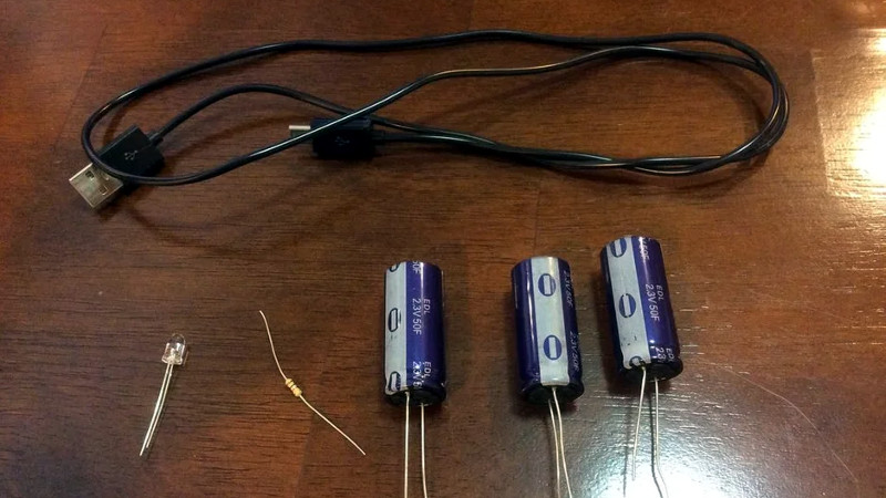
We see what a supercap UPS looks like, but what about one built into a lightbulb or a feature-rich programmable UPS?


“Cheap batteries develop a memory if they’re drained often”
This is an urban myth.
How? By cheaper I am assuming he means tech like ni-cad, which definitely suffers from this.
https://en.wikipedia.org/wiki/Memory_effect
Nicad suffers from memory effect, but people never actually encountered it. What was commonly and erroneously called “memory effect” was a voltage drop due to overcharging and damaging the cells.
Not true, I’ve been caving for years. NiCad was nice compared to lead acid batteries we used to carry. But even well built ones developed memory issues and required the occasional refresh cycle to keep going.
The memory effect is exceedingly obvious when its your light fading intermittently and your mate is smugly able to see what their doing.
With several cells in series, the memory effect presumably occurred slightly differently in each. The light would start off great, then suddenly dim, flicker and then come back to an “OK” brightness. This would repeat till you get fed up and swap the battery pack.
NiMh batteries had a similar but more gentle fall from grace when getting a bit passed it.
Hurrah for lithium and not having to use incandescent lamps anymore.
Talk to any person who flew model planes before LiPo became common, and they will tell you that they encountered it.
Do 2 strokes have memory effect too? :O)
Or they thought they encountered it. As the person you replied to stated, what 99% of people called the “memory effect” was in reality the result if improper charging.
NiMH are far less tolerant to overcharge than NiCd, so it basically forced a move to intelligent chargers with proper charge termination, which eliminated the prevalence of overcharging.
Charging series cells was still a problem though – lots of NiMH chargers didn’t perform individual cell charging and I don’t think I ever saw an RC series pack of NiCd or NiMH with balance leads.
The nice thing about Li-Ion and LiPo being so finicky (as in “overcharge causes fire”) is that a BMS which balances during charge is absolutely required and the same goes for proper charge termination. As a result, far fewer people are getting packs destroyed by bad chargers.
Well it was a thing for older battery chemistries. People for whatever reason still act like it’s a thing.
In any case, a UPS battery isn’t drained often. Most of the time it’s 100% and on a charger anyway.
Not for NiCd it isn’t.
Yes it is, unless it is repeatedly charged to the exact same voltage within millivolts, only found in lab situations and older satellites (mitigated nowdays by adding a variation to charge cuttof voltage).
In equipment available to the mere mortal, what people call memory effect is really just normal wear and tear, usually from cheap crappy chargers.
That sounds somewhat like saying “friction isn’t a thing, what people call friction is really just normal wear and tear, usually from rough surfaces”.
Memory effect and damage from overcharge are completely different things.
I wouldn’t call it “normal” wear and tear. Overcharging isn’t “normal” other than that some older battery chemistries happened to be more tolerant to it. The advantage of LiPo/LiIon’s tendency to catch fire when overcharged is in some ways a good thing – it FORCES people to use chargers with proper termination algorithms and FORCES users of multicell series packs to use a BMS which balances cells. These two things combined would have eliminated 99% of examples of “memory effect” in NiCd but no one wanted to pay for the increased charger cost.
(It helps that the energy density benefits of lithium led to a proliferation of low-cost ASICs for balancing and charging, such that a good charger with cell balancing is a heck of a lot cheaper than it used to be.)
No Its like someone claiming that being at high elevations causes wear an tear on your shoes which is why when you climb mountains you wear your shoes out faster than walking in the mall. when the reality its the friction from climbing the rocks that happen to be more prevalent at higher elevations than in a mall…
IT’s not that the cell has a memory. its that its being damaged b overcharging. has nothing to do with the drain amount.
But NiCd are a thing of the past. In most countries they are more or less banned because of RoHS. NiMH had extreme self discharge for most of the time before “Eneloop” was invented and now I strongly prefer Li based chemistries because the have no self discharge and higher power density.
EVERY battery has self discharge, there is no such thing as a perfect chemistry (entropy will always win in the end). It’s just that lipos tend to have much lower SD than older chemistries of secondary batteries.
“much lower” is a gross understatement :D
where NiMH would be close to dead in 2-3 months, I can pickup a Li-ion pack I left 70-ish % charged a year ago and still use it, this would be impossible with any other normally available rechargeable cell chem.
This is especially beneficial for cordless tools, no longer are packs being discarded just because they were left forgotten on a shelf during the winter and formed metal dendrites, which efectively kill them.
The Eneloop’s claim something like 85% left after 1 year which is fine to me. The normal lithium chemistries are a bit damaged by sitting around at very high or very low states of charge for a year, so it’s not like they’re unaffected.
Curious spaceminions,
What do you observe as “bit damaged by sitting around … very low states of charge..” ?
I’ve not seen much of any problem unless battery hard discharged into low impedance load and runs warm to hot then into a short when not much charge left…
Half correct. Current generation Li-Ion and Li-po batteries do not develop a memory like Ni-Cad’s use to. They still have a finite charge/discharge cycle life span. This is measured differently based on company but the general rule of thumb is the cycle life span is measured in full charge/discharge cycles. Electrolytics do not suffer from either of the above mentioned issues. Electrolytics still have an overall life span based on the degradation of the dielectric fluid used. And heaven help you if you run them over the rated voltage!
Point being, if you don’t have a charge controller, super-caps (with the current limit resistor!) may be the most convenient way to go.
it’s not a ‘memory’, it is a complete lack to perform up to it’s original standards… not a myth, repeatable in modern cell phones, there is a reason people come in asking for a new battery on NEW phones and on NEW laptops. Because their charging profile reads the cell as dead, and they don’t have any motivation to build laptop batteries or cell phones with individual interchangeable cells. It’d be the best idea, standardized batteries, save a crap ton of waste, a crap ton of money, etc. but corporations want that built in death. to the point where they purposely program it into the software. so yeah, it’s not a myth, it’s something that’s designed as part of the product. You really should use a little more nuance when speaking so plainly about “myths” that affect people to the tune of everyone that’s ever used a mobile device.
having said that, you can refurb a single cell if you get it out of the casing, but joe consumer can’t do that. hell, i don’t have time to do it because it’s a pain in the ass to tear apart a laptop battery. For what? a cell that costs a dollar? pfftt… pahleeese.
you obviously havn’t spent any time in the retail trenches seeing how people abuse their batteries.
No u need lab conditions and possibly a chemistry tweak to referb a lithium ion cell. The reason u don’t see it this way (swap one cell) is because if u start putting them in series and one cell has a way higher ir, u get voltage drops and one end is at fire voltage the bad cell 2 from end might try to pull another 15min of cc charge through… And this turns houses and apartments into crematoriums if the controller can’t burn it off/isn’t wise enough to stop charge.
Before u hurt someone please do a bit of homework. 2 or 3 cells odds u get a real shit one and above conditions happen… U probably won’t see it if u just watch charging profiles before putting them in a pack. But that’s a lottery u are playing. If u insist on doing this u need to look up how to messure IR and group cells with similar values (that’s what the factory does).
Also, if u know what ur doing its frustrating as hell but u will find if u let packs go to 0…the bms will blow a permanent switch inside (sometimes external fuse) and that pack won’t work in the device no matter what u do
Also assumption on my part: please don’t disregard above and use a soldering iron. Unless u own ur own non multi family house.. Ie don’t char other people. Spot welders aren’t hard to build. There are reasons the industry uses them. This post is long enough
Well I had a longer reply but I don’t know what happened to it. Please don’t take apart lithium ions and try to swap one cell please don’t do it with a soldering iron if you insist.
Or please read about internal resistance and how to measure it first. Learn about what type of charge controller and Battery management system you’re dealing with. Learn E equals IR. A lot of battery Management systems and charge controllers will balance charges through a decent size resistor that a full cell can bleed off the charge it’s getting if you put a really crap cell like third out ofo4 + you run the risk of possibly burning out the resistor and who knows what happens after that cuz the thing is made in China. The problem is the cells at one end of the pack will be in your voltages where Apartments become crematoriums and that which cell will still want cc charge for 15mim this problem steals with the number of cells you have in your pack especially in series. I want to trust any controller that I haven’t fully read the data sheet and or talk to the manufacturer about what happens if that balancing resistor goes if it’s a large pack it’s better you learn how to match cells based on their internal resistance that’s how the factory does it
Also spot welders can be had for cheap they suck or put some time into learning and you can build one there’s a reason they don’t use solder part of its brittle another part is if you overheat a self you’re going to have problems or just a dead pack again but you’re raising your odds for bad things
Please think twice if you’re doing this in any kind of multi-family dwelling if you have a detached garage in your own home do whatever the heck you want but remember if there’s some one above or below you or through shared wall read four times before you try once. Have a plan for if it goes wrong. Simple things like a cast-iron frying pan under it while you charge it and ideally tile floor or cement under that can go a long way
When you’re talking about UPSes, the most common battery chemistry is still lead acid. While it may not be technically correct to refer to it as a “memory” effect, lead acid batteries definitely lose capacity over time when fully discharged , especially if they’re not engineered for it (not “deep cycle”). Much more so than lithium batteries. So it is a reasonable concern!
UPS batteries are never deeply discharged… This application is nigh perfect for acid lead batteries…
Yup, they’re fundamentally kept topped off in a UPS application – which is as you said one reason it’s ideal for lead-acid.
It’s interesting in that the scenarios where lead-acid degrades severely are the exact opposite of where Li-Ion does. Li-Ion, ideally, should be kept within the middle of its charge range. You get a LOT more cycle life out of a battery if you terminate charge at, for example, 4.0 volts for a cell that has a maximum voltage of 4.2 volts. Do the same to lead-acid and it’ll be sulfated very soon.
The chemistry of Li-ion isn’t completely reversed each time you use it.
Isn’t this a bad idea unless all the capacitor’s ESRs are matched?
In addition, the loading on the USB P.S. would be quite significant / could possibly damage it?
If your power supply can limit the output current for the necessary time it takes for such big capacitance to charge up… because it looks like a short to GND. It also takes quite some time to charge that up… do your math, 50F, 5V and typical 1A PSU, or even a 5A PSU…. plus ESR concerns as mentioned in the post above, also because those caps have current limits which may not be respected by the PSU.
Big problem with supercaps is limiting initial charge
current since it’s basically a short circuit load for milliseconds to seconds depending on capacitance… you can use a CC/CV DC-DC converter or it would be interesting to see the Pi or even an MCU use PWM and a few transistors to “burst charge” it like the equivalent of touching a cap to a battery in quick taps instead of directly connecting them and drawing too much current for too long… and once the supercap voltage is high enough just leave it switched closed in a way that it’s directly connected to the circuit without having a waste power through a limiting resistor or having to design a whole LCR circuit, all you need to know is your power supply’s peak current rating and work out the timing for your caps
Cheap to the rescue! Think about the quality of a typical USB cable: It is a non neglectable current limiting resistor. ;-D
and the USB spec limits how much capacitance a USB device is allowed to have, afair something like 10uf
The 10uF max is to limit the effects of the inrush charging current. In addition, without USB power negotiation, the dumb device is only allowed 100mA.
For a regular PC, multiple USB ports shares overcurrent protection. So plugging this i could affect other USB devices e.g. cause disconnects, and in some motherboards OS shutting down USB devices due to overcurrent detection.
hot plugging with a large capacitance will quickly erode the connector. I’ve had laptops with zero overcurrent protection on usb, shorting 5V usb reset the computer
PWM doesn’t help without some inductance i.e. a dc-dc converter
A few issues with the Instructable/approach:
1. (3) 2.3V 50F Super Caps in series will produce the equivalent of 6.9V 50F, not 6.9V 16.33F as the article states.
2. Connecting Super Caps in series without proper over-charge/over-discharge protection is asking for failures down the road. During charge, the cells can charge to different levels, and potentially exceed the voltage rating. During discharge, it is possible for the cells to discharge differently, and potentially reverse polarity.
3. There doesn’t appear to be anything limiting the charge current to the Super Caps. This can be really hard on the power supply when the caps are at a lower voltage, and can lead to early failure of the connected power supply.
4. This doesn’t appear to use a good portion of the energy stored in the Super Caps. It appears to charge them up to 5V (much less than the 6.9V they could in theory handle), and will probably cut out when there is still quite a bit of voltage/energy left.
A much better design that would solve a bunch of these issues would be to use these Super Caps in parallel with a boost converter module feeding the Raspberry Pi, and a CC/CV buck module charging the Super Caps. This way, the voltage of all the caps will be consistent. The CC/CV will handle limiting the charging current as well as limiting the peak voltage the caps will get charged too. The boost converter will be able to pull out most of the energy out of the cells (depending on which one is chosen). There are plenty of cheap/small boost and CC/CV buck converter modules out there to choose from.
Your point 1) is just plain wrong. If you connect capacitors in series their capacitance is 1/2 or 1/3. Although 1/3 of 50 is 16,67 – a minor inaccuracy. Don’t confuse this with battery capacity in Ah.
The other points are correct.
Ok, I stand corrected on that point #1. Hopefully that doesn’t detract too much from the much more important points that follow.
Not a repost from 2014: https://hackaday.com/2014/04/03/raspberry-pi-ups-using-supercapacitors/
The original article does note “t may take up to a minute or so for the capacitors to charge up”. With the 16.7F capacitance they used, a (say) 1A power supply can only charge at the rate of 4 volts per minute (assuming simple current limiting), so of course it will take a while for your device to see a usable voltage after power on. And your power supply is feeding a short for the duration.
That’s a nutso way to do it, of course.
A very simple solution is to put a small resistor in parallel with a back-biassed schottky diode, and put the pair in the power line to the capacitor. It will charge at the rate limited by the resistor, but permit a high current through the diode when discharging.
Exactly!
Another alternative is to do the capacitance storage on the line side. An easy way to do this is to repurpose a standard big switching supply (they’re cheap, have the appropriate line filtering, fusing, inrush limiting, rectification and big capacitors, and a handy grounded enclosure.) Don’t pick a superfancy power-factor-correcting one for this — all you want is a simple power input front end. Gut the rest of the electronics, even.
Then simply install a normal AC line receptacle into that power supply enclosure, and plumb it into the storage capacitors. It will provide 165 Vdc or 330 Vdc, which any normal supply you plug into it will happily inhale — the first thing a normal power supply does is rectify the incoming AC to that 165V or 330V. You’re just saving it the trouble of that by feeding it DC.
(and just to keep the nannies at bay:) Remember: Safety Third. If you don’t understand what’s involved in what I just said, don’t attempt it.
That sounds like a horribly unsafe and complicated way to do it.
To get to 165V with 2.3V super caps would require at least 72 super caps in series! Not only would that be really expensive and large, it would also require active balancing to safely charge each super cap. Also, you still have to limit the charge current or you will blow a fuse or circuit breaker. Most power supplies take the ac input and run it through a bridge rectifier to feed the supply cap. They may have an NTC ‘resistor’ to help with in-rush current, but this will probably not be enough to deal with the greatly increased capacity super caps would provide.
This would also be really unsafe. The primary-side capacitor in a power supply is the most dangerous part of a power supply. This is because it holds a large DC voltage and can release it rapidly. Converting this to super caps only makes the problem worse, as it would now hold a lot more energy and could potentially release it even faster.
This would also not make good usage of all the energy stored in the super caps, as once the voltage drops a bit, the device you plug in may stop working but there is still a lot of energy left in the caps.
It is much cheaper and safer to deal with this on the secondary side. Use a CC/CV buck module to charge a few super caps in parallel, and use a boost converter to get a regulated output.
Steve, You missed the point, which was to use the existing capacitors and inrush limiter and other certified safe components in the donor supply. It would be dumb (for several reasons, some of which you covered) to use this approach if you were to swap out the electrolytic caps with a huge series of supercaps.
And you also missed the big advantage of using high-side storage: it already has the switcher following it, in the form of the bog-standard power supply you plug into it. Most will happily run down to 100Vdc input.
When operating from a 330V line (which is what supplies with the 120-230V selector switch on them run at internally, even on 120Vac), you’d use in excess of 90 percent of the stored energy in the capacitors before the power supply dropped out.
I love the hell out of this idea. It’s not that dissimilar from WB4APR running his laptop switcher brick straight off his Prius 200VDC traction pack.
I’d definitely try it. Not sure I’d walk away from it…
You want to make sure that your charging circuit is properly designed. The usual NTC or current limiting won’t help you as it’ll take much longer time to charge up the supercap. Also check your protection or switch rating on the PC as AC and DC have different safety ratings.
You’ll find out the cost and the size for the supercap bank is a bit shocking (pun intending).
No, I don’t think I missed the point. I just really don’t agree with the approach.
It is large and expensive and complex (to do it even semi-properly) and dangerous. You are proposing to have a high voltage, high energy source connected directly to an AC outlet that you can plug other devices into. That is taking the most dangerous part of a power supply, souping it up, and providing a much easier path to it. This could easily kill someone. This also effectively removes the circuit breaker’s over-current protection from downstream devices, as they can easily draw an excess of current directly from the supercaps without the upstream breaker tripping.
The built-in in-rush limiter won’t properly handle such a big increase in energy storage created by the supercaps. They are meant to tame the very short burst of current when turning on the power supply. They start with high resistance (a few tens of ohms usually), but quickly drop to a low resistance as they heat up. With supercaps, the required charge current will easily last long enough to heat up the NTC and overpower it, at which point the fuse and/or circuit breaker will blow.
Even though many AC power supplies will run down to 100 Vdc or so, there would still be a lot of usable energy left in those supercaps. They will happily pump out current all the way down to zero volts.
Also, I would love to see a schematic for a power supply that turns 120Vac into 330Vdc on the internal input caps. I could be mistaken, but that does not match my understanding of how they work.
Steve,
I never proposed using supercaps for this application, and even said it was dumb. Yet you persist in wanting to use them here. I’ll say again: it’s dumb. And if you really want to self-abuse yourself into using them then, yes, you’d want to re-engineer the inrush limit, and pretty much everything else too, which defeats the whole purpose of this approach. Again, it’s dumb.
there would still be a lot of usable energy left Dude, running down to 100Vdc from 330Vdc extracts 90% of the stored energy. Do the arithmetic yourself if you don’t believe me. Or if you consider the 10% remaining worth fighting for, have fun at that…
I would love to see a schematic for a power supply that turns 120Vac into 330Vdc on the internal input caps. I could be mistaken, but that does not match my understanding of how they work.
Here: educate yourself. Inspect any of these schematics that use a manual input voltage switch, and you will observe that input goes to a voltage doubler in 120V mode, or direct to the caps in 230V mode. The stored voltage is around 330Vdc. http://danyk.cz/s_atx_en.html
There is a BIG issue with your definition of a UPS. As OP has said, it is something that buys you enough time to gracefully shutdown a PC. Let’s be generous and not ask for anything more than 30 seconds (vs typical 5-20 minutes). Your proposal of using an existing PSU frontend as is problematic.
First off, it is DC output. This means that it won’t work with any active PFC. So you are looking at old school voltage doubler for 120V AC which WON’T work with DC input. :P So you’ll have to toggle the switch to 220V. Once again I have warned about safety rating for fuses, switches are not the same for DC vs AC. They are typically only 250VAC.
Secondly, it won’t get anywhere near the definition of a UPC. It would simply double the holdup time for a PSU which by ATX spec say is 17ms (1 AC period for 60Hz). You would need to have about 1765 times the capacitance. My old Dell PSU (probably 300-ish W) has two 470uF. So that’s about 829,555uF of cap which I would say put it in the range of SuperCap.
Now you see the problem?
BTW non-PFC PSU are not so common with EU power factor requirements.
Sorry make that 414,775uF at 350V as the 470uF caps are in series.
Oh, brother. I’m wasting my breath, but ok, one last kick at the can.
Yes, it provides DC to the user’s power supply. PFC is meaningless, won’t do anything, and not relevant.
The assumption is the user is powering a RasPi-class device. Its wall wart won’t have a switch to worry about, and no voltage selector either: it operates from 85-265Vac. Yes, its internal fuse probably isn’t rated for DC.
The OP’s original application had a usable storage of about 20J. Your 470 uF caps will supply a usable storage of about 10J from 330V. 414,775 uF is not required.
Look at the datasheet of a decent manufacturer’s power supply (like TDK Lambda) You’ll probably find a DC input voltage rating. My bench Lambda has it stamped right on the back. Here’s the first hit I got, for example: https://www.us.tdk-lambda.com/ftp/Specs/rwsb.pdf
And you can bet your ass I wouldn’t plug a random USB charger into a device like this and leave the house for the day. It’s not designed for this use, not certified , not tested, and HVDC has some interesting breakdown mechanisms you can casually ignore at AC. A lowest-bidder chinesium USB wall wart will catch fire sometimes for no reason at all (two have so far for me). I wouldn’t want to give it an excuse.
But this is a useful hack to have in your toolbox. I actually use it to power some xenon strobes, which are very happy at the 330V.
“UPSs became a staple of office workers when one-too-many IT headaches were traced back to power outages.” How many years did it take for folks to check to see if the computer had been turned off?
In my universe the purpose of a USP is to buy time for the computer to perform a graceful shutdown. I once worked in an office where everyone used laptops with batteries but the power brick was plugged into the UPS which was plugged into the wall.
Comprehensive open source UPS project: https://gitlab.com/esr/upside
Supercaps great for starting an internal combustion engine so haven’t used a battery for ages and the caps much lighter. Have 6 off 3000F supercaps in series rated 2.7v ea, been in a Toyota camry 4cyl 2.2L now over 6 years iirc. Only issue is self discharge since I don’t use lights or entertainment when engine not running. They seem to self balance really well. Only use car once or twice a week last 3 years could use a top up solar to 14v though will still start the car with as little as 10v on them…
The voltage will be shared across the series capacitors in proportion to the inverse of their capacitance. Since their capacitance will not be equal, the voltage will not be shared equally.
Supercaps can be very sensitive to overvoltage.
There are app notes around on how to share the voltage more safely.
What a stupid idea, while trying to charge the supercap you may blow the usb port ??
Any legitimate USB port is protected against short circuit and provides current limiting for free. Can’t say the same about some cheaper wall-wart “USB” supplies though.
Some PC actually have overcurrent sense circuit and you’ll actually get an OS USB overcurrent warning and require a reboot to reset the affected USB ports. Google returns 57,600,000 results
Most of the “current limiting” implimentations I have seen are OC-detect or PolyFuse, both of which are going to result in some rather “spikey” on/off “current limiting”.
Far, far far from ideal for this idea.
Isn’t the “memory effect” just where the cadmium grew into crystals inside the battery and thus removed what was available for charge storage?
Very unlikely as the cadmium dendrites would short the battery out making it useless usually. Method to treat it, is slap the battery hard on table few times then hard charge max spec’d current and repeat, worked a few times.
Fwiw. I’ve often dealt with the memory effect of nicads decades ago, best was always to discharge fully. I also observed on doubtful batteries it was quite helpful to freeze battery after full discharge then allow room temp warm up before max rate of charge current battery spec’d to handle…
Useful to weigh new battery before use, then weigh again if it seems capacity down after few cycles, if 5% or more loss then recycle – nothing to do with Einstein ;-)