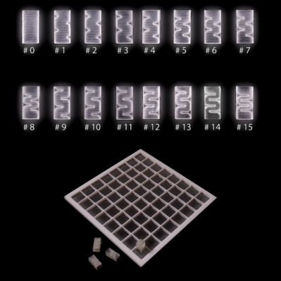
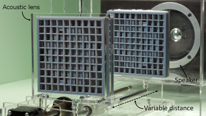
Acoustic lenses are remarkable devices that just got cooler. A recent presentation at SIGGRAPH 2019 showed that with the help of 3D printing, it is possible to build the acoustic equivalent of optical devices. That is to say, configurations that redirect or focus sound waves. One fascinating demonstration worked like an acoustic prism, able to send different notes from a simple melody in different directions. Another was a device that dynamically varied the distance between two lenses in order to focus sound onto a moving target. In both cases, the sounds originate from an ordinary speaker and are shaped by passing through the acoustic lens or lenses, which are entirely passive devices.
 Researchers from the University of Sussex used 3D printing for a modular approach to acoustic lens design. 16 different pre-printed “bricks” (shown here) can be assembled in various combinations to get different results. There are limitations, however. The demonstration lenses only work in a narrow bandwidth, meaning that the sound they work with is limited to about an octave at best. That’s enough for a simple melody, but not nearly enough to cover a human’s full audible range. Download the PDF for a quick read about the details, it’s only two pages but loaded with enough to whet your appetite to know more.
Directional sound can be done in other ways as well, such as using an array of ultrasonic emitters to create a coherent beam of sound. Ultrasonic emitters can even levitate lightweight objects. Ain’t sound neat?


Refraction requires a change in the impedance of the medium, and it’s frequency dependent. In order to get a wider bandwidth, they need to change the impedance much more abruptly, but that leads to reflections rather than passing the sound through.
Same thing for light. Lenses for visible light operate over a very narrow band of the electromagnetic spectrum – a more “universal” lens would simply block light.
I am a lens designer and I’ve designed optical systems for interplanetary exploration, missile sensors, VR and AR head worn displays and digital theater projectors using the Grating Light Valve.
I have a series of designs using swept conics that convert a point source of light into a line of light that has a horizontal field but not vertical. Another design converts a point source into an arc that sweeps horizontally 180 degrees. It has a modest vertical field and a 180 degree horizontal field. All of these use mirrors instead of lenses. They are single mirror transforms. I’m thinking of designing a speaker using this principle (like B&O Beo5 speakers). It’s amazing I got a patent on them since Bang & Olufsen already had one for their Beo 5. But mine covered light, not acoustics.
One version of this uses a parabolic spheroid. It has a parabolic profile if viewed from the side and a spherical profile if viewed from above. A point source is located at the focal point of the parabola, which is also at the center of curvature of the sphere. So it’s diffraction limited in both axis. The result is the point source is converted to a vertical line source right above the focus.
I’m wondering how to model this acoustically. I can do it optically, by making the wavelengths as long as acoustic waves, but I’m not sure if that’s sufficient.
Anyone have any comments or ideas?
Thanks,
Paul
This looks a lot like the experiments that used light to do neural net computations.
If only there was some way to focus microwaves..
Ummm….
https://aip.scitation.org/doi/10.1063/1.5000999
https://www.explainthatstuff.com/radar.html
You’re joking, right?
There are at least six different ways: 1) The obvious parabolic dish or horn, 2) phased array, 3) simple dielectric lens, 4) metamaterial aka metal sheets and styrofoam lens, 5) zone plate and 6) a Rotman lens.
or even a Yagi-Uda, for that matter.
there is, its not much diferent to the setup either. The setup I saw years ago (and i mean years as in using modems to connect to the internet) :)
Basicly it was a polystyrene stack with specially shaped aluminium foil seperators.
Shhh
+1
Do we all get to be let in on the joke?
Can I get .stl files somewhere and try this myself? I have not come up with an application yet, but I just thought it would be interesting to try an acoustic prism or something from this research.
Dammit. This was not meant as a reply. And I can’t edit/remove my comment either…
We made microwave lenses out of styrofoam in uni. Works amazingly well.
Build one’s personal “cone of silence”.
The only news is it can be 3D printed. In the nineteeneigthies i had speakers with acoustic lenses on the tweeters.
… use a doublet to correct for chromatic aberration?
If only England had had this technology during WWI so as early detection of the German Zeppelins and Gotha bombers.
Clearly a troll inviting a response, but I’ll bite anyway.
https://hackaday.com/2017/02/10/acoustic-mirrors-how-to-find-planes-without-radar/
http://www.andrewgrantham.co.uk/soundmirrors/
Do you ever wonder, with modern computer processing, acoustic mirrors could be used to find and track subsonic stealth aircraft?
No need for all that heavy non-steerable concrete nonsense. A modest array of microphones could do the task very easily nowadays. They already are in place for monitoring nuclear testing, and underwater for submarine detection (e.g., the SOSUS arrays).
As Paul said, you dont need any mirrors, you can just use microphone arrays. The issue is that sound travels pretty slowly, and it gets attenuated pretty quickly, roughly -6db per doubling of distance. Assuming the sound of a jet engine is 140dbspl at 1m, it only takes about 10km to get to the level of normal conversation (60dbspl at 1m). Now, according to wiki, a very calm room is about 30dbspl (1m), which would take 320km. Maybe you have a microphone that would reasonably be able to pick this up, and maybe it wouldn’t be completely swamped by every other noise in between you and the jet, but then consider that it would take >16 minutes for you to hear it at 320km. In those 16 minutes, your stealth aircraft has been travelling at 570mph (747 speed) and is now only 75km away.
Not exactly lenses but they had acoustic mirrors.
https://www.thevintagenews.com/2016/07/13/radar-used-giant-concrete-sound-mirrors-detect-incoming-enemy-aircraft/
Looks like this could lead to applications in controlling aircraft noise by using specially constructed materials to direct jet engine sound away from the ground and the passenger cabin.
IIRC, aircraft mfgrs allow for some engine noise in the cabin. I think it is to make it difficult to hear people talking/snoring several rows away.
Zone plates? Do I have to read the PDF?
Can I get .stl files somewhere and try this myself? I have not come up with an application yet, but I just thought it would be interesting to try an acoustic prism or something from this research.
If you read the paper, this work is done in the 7th octave, which is at least 3khz. In their other paper it says 6khz, which is more likely (using harmonics). It’s hardly a feat to make a beamy pattern at this frequency range, all loudspeakers do this naturally. This will also never work at lower frequencies unless the source and lens are scaled larger with wavelength, at which point it is rather impractical.
This is really a disappointment in the tech press, and the authors should tone down the hype. There is no surprise it didn’t appear in a peer reviewed journal.
https://www.researchgate.net/publication/332748253_VARI-SOUND_A_Varifocal_Lens_for_Sound
Just wondering, why did you post that? There’s no original paper there, it’s just a researchgate link to the reference.
FWIW, I do have a copy of the original paper, and my comments are correct. There’s nothing notable about creating narrow patterns from loudspeakers, they do this naturally. This experiment was done at 6kHz, and it won’t work at lower frequencies at all.