[Hesam Moshiri] has built a variable switch-mode power supply over on hackaday.io. When prototyping a new circuit, often the goal is to get a proof-of-concept working as soon as possible to iron out all of the bugs it might have. The power supply can easily be an afterthought, and for smaller projects we might just reach for an adjustable LM317 voltage regulator to dial in the correct voltage and then move on with the meat of the project. These linear regulators are incredibly inefficient though, so if you find yourself prototyping with one of these often enough, it might be worthwhile to switch to something better.
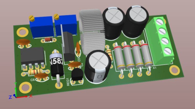
While it’s easy to simply buy a switch-mode power supply (SMPS) that has everything you need, and rated for 90% or higher efficiency at the same time, getting one with an adjustable output isn’t as easy. This one is based on the relatively popular LM2576-Adj chip which handles the switching frequency part of the circuit automatically. You will also need some large capacitors, an inductor (one of the disadvantages of an SMPS circuit) and a small potentiometer to use as the feedback control for the LM2576. This special pin allows the output voltage of the SMPS to be precisely controlled.
Granted, this project might not be breaking any new grounds, but if you’ve never given serious thought to your small breadboard circuit power supplies, it’s definitely worth looking into. An improvement from a linear regulator’s 30% efficiency to 90% efficiency from an SMPS will not only save you a ton of energy but also solve a lot of heat dissipation problems. If you don’t want to build a switch-mode supply 100% from scratch, though, it might also be possible to modify an existing one to suit your needs as well.


has anyone seen a schematic and/or built a dual rail supply with the LM2576?
I’ve found a few schematics for inverting supplies, but not dual rail
it can’t be as simple as just using two LM2576s, can it?
If you use a line choke or transformer in place of the inductor you can generate dual voltages from one LM2576 SMPS circuit. Not good for much current, but great for instrumentation amps.
A switcher for an instrumentation amp supply? Sounds like a recipe for much pain, or your app doesn’t care much about noise. You could follow it with a low dropout linear though, which helps enormously.
FYI: https://hw-by-design.blogspot.com/2018/08/audio-sw-analog-power-supply.html
I have implemented a +/-5V analog supply for my audio project. The -5V is generated from a parasitic charge pump from a $0.50 switch mode buck module with ferrite and linear regulator. The layout pays a significant role as I had to provide a shorter return path for ground to reduce noise.
tl;dr It is possible to run analog circuit from noisy SMPS if you know what you are doing. I have captured scope pictures showing the noise at various stages.
The trouble with SMPS is that the efficiency drops when you draw less current, as opposed to linear regulators which come in versions that draw essentially zero current when you’re not drawing any yourself. This is essential for any battery operated device without a physical battery cut-off switch, or a sensor that needs power only intermittently.
Eg. MAX882 goes down to 11 uA at idle, 7 uA at standby and 1 uA when switched off. Try that with an SMPS.
Uhh, the LTC3525 is a nice little switcher that idles at 7 uA, can deliver 400 mA, up to 95% efficiency, and has been around for 15 years.
Usually they have a standby mode that low, but then the chip is not switching and you have no output. The LM2576 in the article has a minimum current draw at around 90 – 100 uA with the output on.
Then you have to add to that the leakage current of the input and output capacitors, which need to be sized much bigger for an SMPS, which means more leakage again.
Then there’s also the curious effect where large electrolytic caps keep an additional 50-150 uA leakage current for about 5-10 minutes after a suitably large ripple current has gone through, before they settle back down to their operating leakage current. This does not happen with linear regulators because there’s negligible ripple current.
I’ve had to deal with these effects with IoT sensors and radios that have to idle most of the time and wake up every 5 – 15 minutes, consuming around 250 uA on average for the entire circuit. If I used the LM2576 for the power supply, it would halve the battery life.
As suspected. Read the datasheet on the quiescent current:
“Note 4: Current Measurements are performed when the LTC3525 is not switching.”
The actual no-load input current goes up to 43 uA with falling battery voltage. That’s largely because this is a step-up converter rather than step-down as in the article, so it’s a bit of apples to oranges anyways. There are no linear step-up converters.
That’s the neat thing about the LTC3525: it doesn’t switch when there’s no load. As long as you have decent caps (electrolytics need not apply), it runs a very tiny duty cycle maintaining the output voltage.
But, yeah, not applicable for this application: it’s boost only and fixed output voltage.
Yet the datasheet provides a graph for the no-load situation, which shows that it consumes much more at idle than the claimed 7 uA. Something to keep in mind nevertheless.
The trouble is that you have to look harder.
MCP1640C, and others from that family are the way to go for Alkalines and primary cell, non-rechargeable batteries–You can turn them off and they act as a direct pass through from battery to your product.
You can’t make relative “good” or “bad” decisions without more information about a particular application.
Many modern SMPS chips include a PFM mode now for low current loads.
The PFM mode operates at lower frequency which can be harder to filter for analog applications. I learnt this the hard way. There are PWM only version of the chips with the same pinout.
If you think you hear a high pitched whine coming from a non-isolated buck regulator, it’s not your imagination. Many of these devices adjust switching frequency lower when light loads occur to maintain regulation. An ST ViPER part from a few years ago would reduce its switching frequency down to 7.5kHz under the lightest load conditions, well into the human audible range.
That is true for some parts, like the early ViPER series from ST. When used in a non-isolated AC-DC buck application (where the product is designed so that the user cannot come into contact with ANY electrical components), the ViPER would reduce its switching frequency to about 7.5kHz under the lightest of loads. That is easy to hear as ceramic caps and the inductor would emit audible noise.
That is NOT true for more modern PFM regulators that essentially use a “burp” mode for regulation, that is, they only switch at their high frequency, but do so in bursts.
The “burp” is even more annoying, because the burst rate shows up as ripple through your analog circuitry, and it’s even more difficult to filter out.
The particular part I am taking about is the Microchip boost part and not the ST ViPER. Really not care about audio noise, but electrical noise is the problem.
Sadly the low frequency of itself introduce low frequency noise into the power rails which are very hard to filter with passive components that was already in my PCB layout. It shows up in the FFT plots when I analyse the data with a wide spread in the low frequency that ruin the data.
With a PWM version, the switching frequency is well above the analog signal and it was easily filtered with a ferrite LC filter and the anti-alias filter. The noise doesn’t show up in the plot.
PWM switching frequency does not depend on load – only duty cycle changes. frequency remains high.
PFM – pulse skipping s highly dependent on load. Even if it runs in burp mode, the ripple is higher and is modulated with a low frequency component.
While you could use a LDO with a decent ripple rejection to ilter it at the lot of efficiency (need slightly higher voltage and higher quiescent current) and complexity. in the end, PWM only version make more sense.
But that’s again a step-up regulator, not a step-down regulator. Apples to oranges.
SMPS are like flushing the toilet but instead of pressing the button you walk to kitchen, take a glass of water, pour it from 2 stories and rinse repeat until the bowl (capacitor) is empty and fecal matter (electric noise) is all around.
“You will also need […] an inductor (one of the disadvantages of an SMPS circuit) […]”
For newbies, could someone explain why needing an inductor is a disadvantage? And also what are other disadvantages of SMPS circuits (other than higher current draw when you draw little current like Luke described).
Switchers take more parts (inductor, usually a diode, often a charge capacitor for powering the gate of the internal switching fet) and put noise on their output, and want a nice layout, which linears don’t care about much or at all. But their efficiency sure is nice and many of them have enable/disable pins so you can shut them off when they’re not needed. Plus you can get ones that can take an input of, say, 65 down to 3 volts and produce 5 volts out regardless. I’m working with one we just designed at work that has over 95% efficiency from 10% up to 99% load.
SMPS disadvantages:
– Because you have a clock greater than 9kHz, hello FCC Part 15B testing.
– When voltage is instantaneously applied across an inductor, the current through the inductor starts low, then ramps up until the SMPS turns off the transistor, then the current continues through the inductor but ramps down. This ramp up / ramp down saw tooth is a ripple current. The ripple current is driven through the inductor and into an output capacitor to smooth out the ripple. Unfortunately real electrolytic capacitors are not ideal and have parasitic elements in them. For larger SMPS, the resistive parasitic element in the capacitor * the ripple current makes a ripple voltage. (V = I * R). The ripple voltage will go above and below your DC output level, for example 100mV ripple means your 5VDC output is actually 5VDC with 100mV ramping up and down at the switching frequency of the SMPS. This noise high frequency ripple would be coupled into your analog circuits. This is why SMPS circuits need significant filtering when used with analog circuits. This is also why Micrel, now Microchip developed their RippleBlocker type LDO regulator.
– Because we are switching square waves at a relatively high frequency of 100kHz+, we are generating higher frequency harmonics, into the areas where the FCC starts caring about the radiated emissions from you product. Pro-tip, always use shield inductors, and always make high dI/dt or dV/dt paths as short as possible. The shorter the path, the less it effective an antenna to radiate out noise at a high frequency harmonic (multiple) of your SMPS switching frequency.
– Cost. It’s really hard to get cheaper than an LM317, or LM7805 though the MC33063A is close.
-Peukert’s Law. It applies to alkalines as well. You are ALWAYS better off (in terms of battery life) stepping voltage down than stepping it up when being powered by batteries.
Note for LDOs: Some LDOs have stability issues when used with ceramic capacitors — YOU HAVE TO MAKE SURE YOUR REGULATOR OPERATES IN A STABLE REGION! An example is the LM2850. You can use a regulator like this with ceramic capacitors, but often a resistor is needed in series with output capacitor to prevent the LDO from oscillating. Some of the linear regulators were designed many years ago with aluminum electrolytic capacitors in mind, and those capacitors have orders of magnitude more ESR than ceramic capacitors.
One SMPS advantage is that you can make one with a microcontroller, as long as the microcontroller has built in analog parts (comparators, flip-flop, S-R latch) that can operate without the CPU. Microchip has some special purpose MCUs with this in mind. In that case you could power the MCU from the batteries directly, and have the MCU turn on the discrete boost regulator as needed.
I’d like to point out something about swtiching frequencies: the frequency of the highest significant harmonic depends on the switching speeds (rise and fall times), not switching frequency. If you have a 100 kHz switching supply, it can generate spurious signals every 100 kHz, up to VHF frequencies, easily. If you have a 1 kHz switching supply using the same rise and fall times, it can generate spurs every 1 kHz, again well into VHF. This was illustrated to me recently when I had some 12V LED lighting that completely wiped out the HF band on my shortwave radio. The dimming was being done by a microcontroller module switching at just a few kHz.
Operating at “low frequencies” doesn’t make you non-intrusive.
Unless you can get an off the shelf inductor, beginners seem put off by winding inductors, so they may perceive sonething needing one as “too co.implicated” .
I’ve noticed that with RF coiks, but switchers need much larger coils, though since they are for relatively low frequencies, one can be messier than when winding a low inductance clil.
Michael
You do realize you can get nice little switchers that will take up to 36V in and give you up to 32V out at an honest amp, and go for about 50 cents a pop on eBay. They have tiny and very efficient, 90+ % doing 5 to 3.3V. The only downside I have observed is the Vout adjustment posts are single turn and the smallest trimpots I have ever seen in my life.
I use these for anything except anaog use. They are priced similarly to popular 3 pin regulators and are small enough they can be put in their place.
The silicon is good up to 65V (at least on TI/what used to be National Semiconductor switchers), but I’m dubious that their input and output caps are actually the rated voltage they claim they are.
Also beware of some “fake” chips that are the older version of the SMPS that runs at a much lower frequency. i.e. more noisy output. They removed the original part marking and use a laser to engrave the new one.
I’m not sure where anyone gets the idea that “variable” is hard to come by. They’re all over the place, and cheap.
Not only are they all over the place, but all regulator circuits, including 3-terminal devices, can be modified to change their output voltage, by the addition of a resistor or two in the feedback path.
For a !ot of small projects, a tiny transformer orobab is as simple a solution as anything. There was a time when I’d pull small transformers out of c!ock radios and such, because a transformer coukd add significantly to the price of a small project.
Then AC adapters became common, certainky advantages there.
And now small external switching supplies are tge norm, so often one can scrounge. One tine when I needed a 24vdc supply fora Mac Powerbook, I opened a scrap inkjet printer and found just the right switcher inside, it was even on its own board.
Now the norm is 5v usb adapters, which works for some projects.
Michael
“getting one with an adjustable output isn’t as easy.”
What rock have you been living under? $2 on ebay..