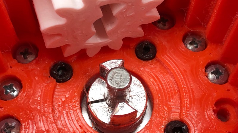
Interfacing a shaft to a 3D printed gear doesn’t have to be tricky. [Tlalexander] demonstrated a solution that uses one half of a spider coupling (or jaw coupling) to create an effective modular attachment. The picture above (and this older link) shows everything you need to know: the bottom of the coupling is mounted to the shaft, and a corresponding opening is modeled into the the 3D printed part. Slide the two together, and the result is a far sturdier solution than trying to mate a 3D printed gear directly to a motor shaft with a friction fit or a screw. This solution isn’t necessarily limited to attaching gears either, any suitable 3D printed part could be interfaced to a shaft in this way.
 These couplings are readily available, and fortunately for hobbyists, come in sizes specifically designed for common stepper motors like NEMA 17 and NEMA 23. Ironically, these couplings are often used when building custom 3D printers for those same reasons. With this method interfacing anything at all to a motor shaft becomes mostly a matter of modeling a matching hole out of the part to be 3D printed. One coupling even provides two such attachments, since only one of the two sides is used.
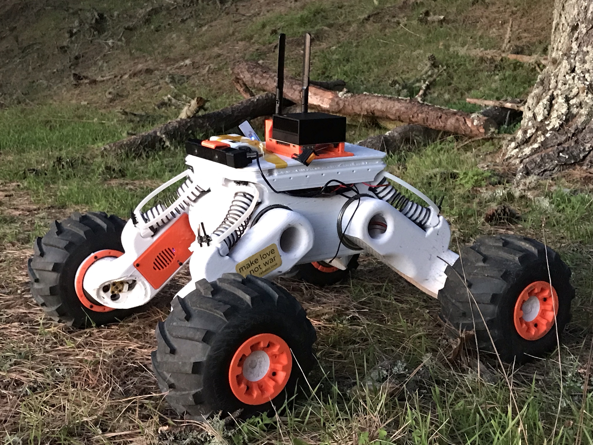
The image up top is from [Tlalexander]’s Rover image gallery, which contains a ton of fantastic pictures of the work that went into the gearboxes, a major part of the Rover’s design that we’ve seen in the past.


A+ in the art of misusing parts.
AKA,
Double Plus Good.
This strikes me as a cunning idea that hadn’t occurred to me.
But now that I have been prompted to think about it I am wondering if there is anything else out that that is potentially better.
One thing missing with this approach is axial location of the 3D printed part on the coupler hub.
I guess that epoxy to hold the hub into the gear would be a good solution, though that might be tricky as the design shown does look like it rather depends on the motor shaft to keep the part square to the coupling.
Drilling and tapping the flat face between the prongs would be a solution, were it not for the presence of the split and the clamp screw.
It has become quite common to melt threaded inserts intended for injection moulding in to 3D printed parts, and Gwgling has indicated that many gears are injection moulded around a hub, but I haven’t managed to find loose hubs intended for the task.
Provided you insert/locate a shaft in advance, you could melt insert the half coupling into the part.
you could also mount the coupler upside down, which would lock the 3d printed part. (the 3d printed part would then need a hole to tighten the coupler however)
I’ve sheets used cheap extruder gears , any metal gear gives you lots to grab onto.
Mount the part on the axle, crossdrill the axle, insert roll pin (or similar). Done. The coupler should still take the brunt of the torque, the roll pin will provide axial locating. If something stronger is needed, let more of the axle stick through and thread the end, then you can mount a washer and nut to clamp the part to the coupler axially.
An easier solution just occurred to me. Print a recess in the back side to expose a few mm of the shaft and fit a starlock washer.
Sandwich the printed gear between TWO couplers.
You’ll have to figure out how to attach the couplers to each other. The other coupler is usually attached to another shaft.
I don’t use the word ‘hero’ lightly…
This would also be a good idea for protecting the motor from overload: a 3d printed part could break before doing any damage to the more expensive components.
Not very likely:
https://hackaday.com/2019/08/20/behold-the-crimson-axlefcker-do-not-insert-finger/
This looks like half of a plum coupler.
Additive Metal Engineer here and Additive Manufacturing is about cost of CNC operations vs cost of metal printed part finishing. Clamps and Collars need much post printing CNC process and finishing. Not much savings
I used something like this:
https://us.misumi-ec.com/vona2/detail/110302153230/
You can attach things bigger than a gear.