Nothing can ruin a restoration project faster than broken knobs. Sure, that old “boat anchor” ham rig will work just fine with some modern knobs, but few and far between are the vintage electronics buffs that will settle for such aesthetic affrontery. But with new old stock knobs commanding dear prices, what’s the budget-conscious restorationist to do? Why, fix the cracked knobs yourself, of course.
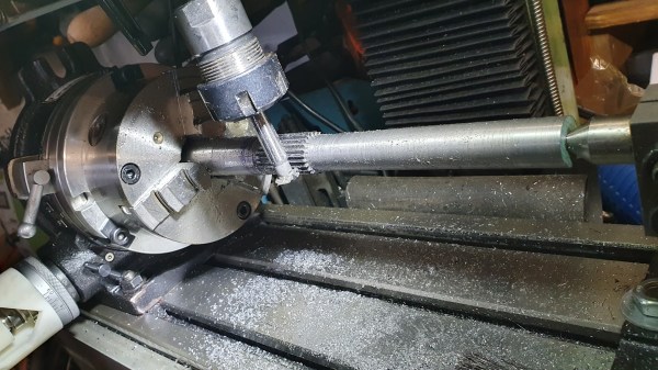
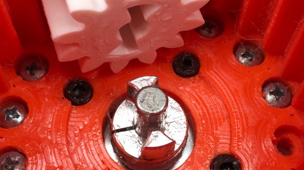
At least that’s what [Level UP EE Lab] tried with his vintage Heahkit DX60 ham transmitter, with pretty impressive results. The knobs on this early-60s radio had all cracked thanks to years of over-tightening the set screws. To strengthen the knobs, he found some shaft collars with a 1/4″ inside diameter and an appropriate set screw. The backside of the knob was milled out to make room for the insert, which was then glued firmly in place with everyone’s go-to adhesive, JB Weld. [Level UP] chose the “Plastibonder” product, which turns out not to be an epoxy but rather a two-part urethane resin, which despite some initial difficulties flowed nicely around the shaft collar and filled the milled-out space inside the knob. The resin also flowed into the channels milled into the outside diameter of the shaft collars, which are intended to grip the hardened resin better and prevent future knob spinning.
It’s a pretty straightforward repair if a bit fussy, but the result is knobs that perfectly match the radio and still have the patina of 60-plus years of use. We’ll keep this technique in mind for our next restoration, or even just an everyday repair. Of course, for less demanding applications, there are always 3D printed knobs.
Continue reading “Steel Reinforcement Toughens Cracked Vintage Knobs”