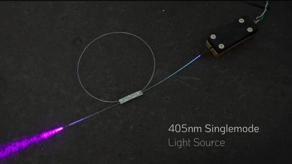
Properly Pipe Laser Light Around With Homebrew Fiber Couplings

It’s a rare person who can pick up a cheap laser pointer and not wield it like a lightsaber or a phaser, complete with sound effects. There’s just something about the “pew-pew” factor that makes projecting a laser beam fun, even if it’s not the safest thing to do, or the most efficient way to the light from one place to another.

We suspect that [Les Wright] has pew-pewed his way through more than a few laser projects in his lab, including his latest experiments with fiber coupling of lasers. The video below is chock full of tips on connecting cheap communications-grade fiber assemblies, which despite their standardized terminations aren’t always easy to use with his collection of lasers. Part of the challenge is that the optical fiber inside the cladding is often very small — as few as 9 microns. That’s a small target to hit without some alignment help, which [Les] uses a range of hacks to accomplish.

The meat of the video demonstrates how to use a cheap fiber fault locator and a simple optical bench setup to precisely align any laser with an optical fiber. A pair of adjustable mirrors allow him to overlap the beams of the fault locator and the target laser precisely. The effects can be interesting; we had no idea comms-grade fiber could leak as much light through the cladding as this, and the bend-radius limits are pretty dramatically illustrated. [Les] teases some practical sensing applications for this in a follow-up video, which we’re looking forward to.

Looking for more laser fun with your remaining eye? Check out [Marco Reps] teardown of a 200-kW fiber laser.

Continue reading “Properly Pipe Laser Light Around With Homebrew Fiber Couplings”

Bricking Your 3D Printer, In A Good Way

In our vernacular, bricking something is almost never good. It implies that something has gone very wrong indeed, and that your once-useful and likely expensive widget is now about as useful as a brick. Given their importance to civilization, that seems somewhat unfair to bricks, but it gets the point across.

It turns out, though, that bricks can play an important role in 3D-printing in terms of both noise control and print quality. As [Stefan] points out in the video below, living with a 3D printer whirring away on a long print can be disturbing, especially when the vibrations of the stepper motors are transmitted into and amplified by a solid surface, like a benchtop. He found that isolating the printer from the resonant surface was the key. While the stock felt pad feet on his Original Prusa i3 Mk 3S helped, the best results were achieved by building a platform of closed-cell packing foam and a concrete paver block. The combination of the springy foam and the dampening mass of the paver brought the sound level down almost 8 dBA.

[Stefan] also thoughtfully tested his setups on print quality. Machine tools generally perform better with more mass to damp unwanted vibration, so it stands to reason that perching a printer on top of a heavy concrete slab would improve performance. Even though the difference in quality wasn’t huge, it was noticeable, and coupled with the noise reduction, it makes the inclusion of a paver and some scraps of foam into your printing setup a no-brainer.

Not content to spend just a couple of bucks on a paver for vibration damping? Then cast a composite epoxy base for your machine — either with aluminum or with granite.

Continue reading “Bricking Your 3D Printer, In A Good Way”

(Mis)use This Part To Attach 3D Printed Stuff To A Shaft

Interfacing a shaft to a 3D printed gear doesn’t have to be tricky. [Tlalexander] demonstrated a solution that uses one half of a spider coupling (or jaw coupling) to create an effective modular attachment. The picture above (and this older link) shows everything you need to know: the bottom of the coupling is mounted to the shaft, and a corresponding opening is modeled into the the 3D printed part. Slide the two together, and the result is a far sturdier solution than trying to mate a 3D printed gear directly to a motor shaft with a friction fit or a screw. This solution isn’t necessarily limited to attaching gears either, any suitable 3D printed part could be interfaced to a shaft in this way.

These couplings are readily available, and fortunately for hobbyists, come in sizes specifically designed for common stepper motors like NEMA 17 and NEMA 23. Ironically, these couplings are often used when building custom 3D printers for those same reasons. With this method interfacing anything at all to a motor shaft becomes mostly a matter of modeling a matching hole out of the part to be 3D printed. One coupling even provides two such attachments, since only one of the two sides is used.

The image up top is from [Tlalexander]’s Rover image gallery, which contains a ton of fantastic pictures of the work that went into the gearboxes, a major part of the Rover’s design that we’ve seen in the past.