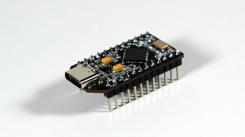
USB-C versus USB Micro connectors are turning into one of the holy wars of our time. Rather than be left on the wrong side of the divide [Stefan S] has come up with his own USB-C version of of an Arduino Pro Micro to avoid having to always find a different cable.
Home made Arduinos come in all shapes and sizes from the conventional to the adventurous, and from the pictures it seems that this one is firmly in the former camp. The USB-C is present in connector form alone as the device is only capable of talking at the much slower speed of the ATMEGA32U4 processor, but having the newer connector should at least make cabling more accessible.
This is one of the most practical Arduino clones we’ve ever seen, but one of our other favourites is also a bit impractical.


USB C ALL THE THINGS! \o/
They are more durable then microusb so, yeah
everyone says that then never backs it up, I have never broken a micro or a c type cause I take care of my shit, so in reality I rather have micro cause I have a billion cables and like 2 usb c cables
Quality USB-C cables have extruded shields instead of stamped, while I’ve never seen an extruded MicroUSB type-B plug – always stamped.
What the heck does that have to do with anything
Because the stamped micro-USB connectors have a seam in them, so they can deform pretty easily, and then trying to plug it in will deform the receptacle as well. The extruded USB-C connectors take a lot more to deform them.
And even if you are super-careful and inspect every cable you have before plugging it in, not everyone is, and it’s extremely helpful to have a more robust connector to protect against *other people*.
You want the cable’s connector to be weaker than the phone’s connector, that’s actually one of the design goals. So when one or the other has to give, it’s the $2 cable, not the $1000 phone. Seeking out the most robust cable is counterproductive.
Not extruded, but the Monoprice Premium Micro USB cables use a *vacuum die cast* Micro connector. Probably the best in the industry, no foolin’. These connectors are gold plated and do not screw around. I got so sick of wondering, “is it the cable or the bootloader?” and so batch-replaced all my USB cables with these. Best decision I ever made in the last decade, easy. The connectors are made on some sort of German vacuum die-casting machine; I’ve never seen these anywhere else. Truly a Micro connector for the ages.
You will eventually drown in your billion USB cables and dongles, trying to find the right one, when the rest of us can use our 2 USB C cables for everything we need. How much of your life do you spend keeping your pile of USB cables from taking over? Why don’t you have the ability to get rid of what you don’t use?
Until the next “USB C” hits and all of a sudden the current connector “sucks” and we have to upgrade to the new standard. It’s a never ending cycle.
My cables are leftovers from long ago obsolete to used to death devices there’s only 1 device in the house that uses c and its this (pos) lg phone which makes it the odd man out and its a pain in the ass with the only benefit so far is not having to try 3 times before plugging it in
My wife’s Pixel phone lasted more than two years, so I’m certainly sold on USB c! I know it’s anecdotal, but she’d break a micro every year.
And here I thought that was sarcasm until I read the second sentence :)
S**t yes. Just this week I’ve had micro-USB connectors snap off TWO cheap Arduino Pro Micro boards, pads and all! Argh! 😫
while regular USB power delivery was pretty much limited to 5V, usb C can deliver legitimately up to 30V, so i’d be a bit cautious with the ‘one cable to rule them all’ approach.
In theory if the device communicates at older USB 2.0 or 1.1 spec, the host will only supply 5v.
yea im sure this is following spec to the letter
I thought USB PD was limited to 20V max at 5A delivering a whopping 100 W. Still very amazing. Perhaps the new 3.0 version is able to output at 30 V but what makes USB PD special is the ability to adapt to different devices with different voltages and current through digital communication.
Your first thought is right, 20 V is the max, even with USB PD 3.0. (Actually 21 V using a PPS APDO, but why push it?)
Source: I’m the lady who made the PD Buddy Sink, so I’m intimately familiar with the enormous standard that is USB PD.
Hopefully the USB C plug are wired correctly to work with cable in either direction. Unlike Raspberry Pi!
The pi fails to negotiate for higher power on intelligent (pd capable) supplies.
I was not aware that it also does not support a reversible plug.
I’ve never heard of an issue with the Pi 4 being picky about cable orientation, and I got my Pi 4 pretty much on release day and I’ve never had orientation issues. Misunderstanding, perhaps?
The pi will work the same with the cable either way up, The main problem with charger compatibility on the pi is that the CC lines are connected together which causes it to be misidentified by chargers as an audio device (which shouldn’t be provided with power) when connected using an emarked cable.
This is worst than that the CC pins are not connected to anything
Y’all over here arguing about Micro vs Type C, and I’m just over here enjoying the simplicity and longevity of my mini connectors.
Mini connectors? I remember them, they fall out so well.
I wish people stopped using Arduino as a way to advertise their products.. This is not an Arduino Pro Micro.. it’s a pcb with a Microchip processor on it… Hackaday please be less sloppy :)
It won’t work with any USB-C to USB-C cable as the CC pins are unconnected.
https://cdn.hackaday.io/files/1674547164351936/Schematic.pdf
Indeed. Kinda sad that people don’t even add the two 5.1k resistors… Why don’t people just read the application notes that are out there and follow them? It would have been so easy to get it right the first time…
One of the downsides of PCB design being so “easy” now is that people who have genuinely no idea what the components they’re connecting together actually do or how they really work beyond what the schematics they Frankenstein together show.
I miss USB Mini-B.
Mini USB- B is about my fav too. C has proven to be only slightly better then micro-B in terms of ruggedness. Advantage C for power and reversible insertion but it wears out like micro and if not properly mounted both micros can rip up traces. Ideally any of them should be mounted on replaceabe daughter boards. Space and cost allowing.
There’s a similar project I found while researching – Dr-Derivative’s Goldfish. It’s a Pro Micro clone with USB-C. It was made for QMK keyboards and has a few revisions under its belt.
I don’t know what was wrong with 25D RS232 plugs, you knew where you were with those.
Though, once, I did see a VGA connector that had been “almost” plugged in 180 degrees.
I suppose the so tiny USB-C is the best for mobile phones but I don’t see it solders well on a PCB and fear it will break from the PCB more easily than micro USB. Not the good solution for standalone PCBs.
I just soldered my USB-C connectors recently. The USB-C connector still has large anchor pads like any other connector, so the metal frame is soldered to the PCB. Zoom into the picture on this article and you’ll see the little legs going from the metal frame to the PCB.
would be even better if it was a USB C plug so I could plug it straight into my mac