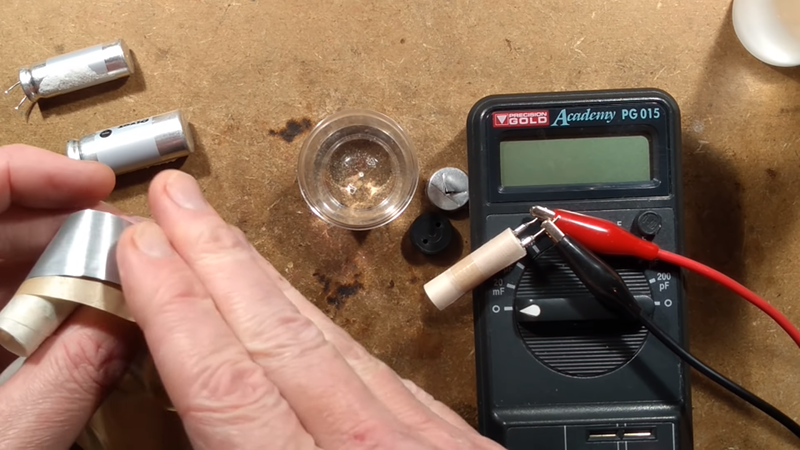
Making a capacitor is pretty easy. Just get two conductors close together. The bigger area you can get and the closer you can get them, the bigger the capacitor you can make. [BigClive] found some fake capacitors that were supposed to be very high value, but weren’t. Taking them apart revealed the capacitors didn’t have the electrolyte inside that gives these units both their name and their high values. What did he do? Mixed up some electrolyte and filled them back up to see what would happen. You can see the video below.
Electrolytic capacitors have a secret weapon to get the two electrodes as close as possible to each other. The electrolyte forms a very thin insulating layer on one electrode and the capacitance is between the conductive fluid and that electrode — not between the two electrodes. This allows for a very narrow gap between the conductors and explains why a small electrolytic can have a much greater capacitance than most other technologies in similar form factors.
There are other tricks at play, too. For example, the anode side of the capacitor is usually etched or otherwise roughened to provide more surface area than a similar flat material. During manufacturing, a forming voltage causes the oxide layer to form and also sets a polarization on the capacitor. Reversing current through the device is likely to cause a short and quickly destroy the device.
Did [Clive’s] homemade electrolyte of boric acid and antifreeze work? Sort of yes and sort of no — watch the video and find out. Understanding how all this works can help you repair old electrolytics. Every once in a while, we toy with making our own capacitors for educational purposes or very high voltages.


Al Williams, it seems that you embedded a video with a timestamp in the link – it starts at 13 minutes. If that wasn’t intentional, you might want to remove the timestamp from the video embed link.
I hoped that this would be some sort of “someone tries restoring old puffy electrolytics instead of replacing them” video, but I’m not disappointed, this is an interesting topic!
s/hoped/thought/
Not sure how that happened, but fixed now. Thanks.
No wonder it failed. He applied power across the cap without a power limiting series resistor.
Watch the whole video first. Series resistor was initially used, the embedded portion only shows last test.
Any I reformed had to sit at least overnight, and I always used a high enough value series resistor so the cap could not over heat.
As always from Big Clive, lovely video.
Also, the makers of the wonderfull little transistor tester are not forgotten.
https://hackaday.com/2015/04/24/review-transistor-tester/
which mentions:
https://www.mikrocontroller.net/articles/AVR_Transistortester
And also firmware and collected schematics of different versions (also in different repositories) on github. For example, this PDF has around 20 different LCD’s in it:
https://github.com/Upcycle-Electronics/AVR-Transistor-Tester/blob/master/Final%20Draft%20LCD%20Master%20Transistor%20Tester.pdf
And these are worth buying just for the uC + LCD, as has also been posted on Hackaday, in an article about some car radio thing.
I saw the video – quite interesting. But when he worries about bubbles, I think it was just the developing hydrogen, which is an integral part of the forming process.
And I think I read, that for the forming process at the factory a different electrolyte is used than for the operational capacitor. The first one should allow easy electrical oxidation of the foil thus be more chemically active. The second one should be quite inert to give the cap a long live time.
The video certainly helps understanding Elco’s better.
The (very thin) oxide layer is the insulating part and the etched foils siginificantly increase surface area (which is only mentioned very briefly by Clive).
It seems logical that one of the two foils is etched / formed / oxidized in the factory before assembly, Hydrogen release would not be an issue then. (Water is H2, oxygen used to make the oxide, but Clive does not use water?)
The electrolyte is conductive and only has to transport the electrons to the “other” foil, (which is not ozidized).
This does make me wonder though why there are 2 different kinds of paper in the capacitor.
Maybe it is becasue of an unrelated issue, such as the foils having slight burrs from cutting and thicker paper is used on the burr side. But I’m guessing here.
I also wondered about the two kinds of paper – I thought you definitely want to use both surfaces of the electrodes.