Leaky SMD Electrolytics? Try These Brute Force Removal Methods

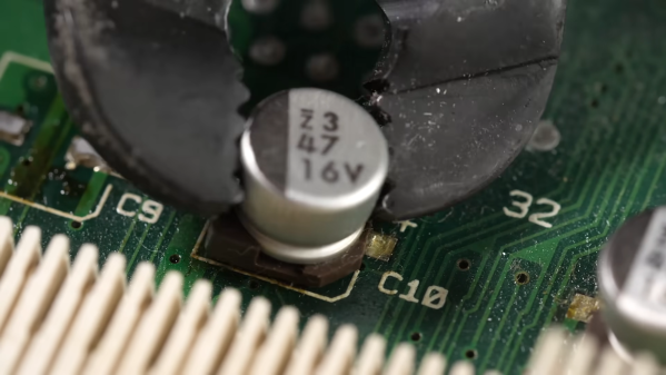
When you say “recapping” it conjures up an image of a dusty old chassis with point-to-point wiring with a bunch of dried-out old capacitors or dodgy-looking electrolytics that need replacement. But time marches on, and we’re now at the point where recapping just might mean removing SMD electrolytics from a densely packed PCB. What do you do then?

[This Does Not Compute]’s answer to that question is to try a bunch of different techniques and see what works best, and the results may surprise you. Removal of SMD electrolytic caps can be challenging; the big aluminum can sucks a lot of heat away, the leads are usually pretty far apart and partially obscured by the plastic base, and they’re usually stuffed in with a lot of other components, most of which you don’t want to bother. [TDNC] previously used a hot-air rework station and liberally applied Kapton tape and aluminum foil to direct the heat, but that’s tedious and time-consuming. Plus, electrolytics sometimes swell up when heated, expelling their corrosive contents on the PCB in the process.

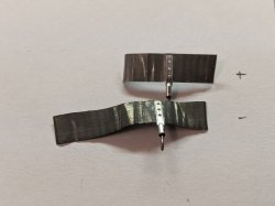
As brutish as it sounds, the solution might just be as simple as ripping caps off with pliers. This seems extreme, and with agree that the risk of tearing off the pads is pretty high. But then again, both methods seemed to work pretty well, and on multiple boards too. There’s a catch, though — the pliers method works best on caps that have already leaked enough of their electrolyte to weaken the solder joints. Twisting healthier caps off a PCB is likely to end in misery. That’s where brutal method number two comes in: hacking the can off the base with a pair of flush cutters. Once the bulk of the cap is gone, getting the leads off the pad is a simple desoldering job; just don’t forget to clean any released schmoo off the board — and your cutters!

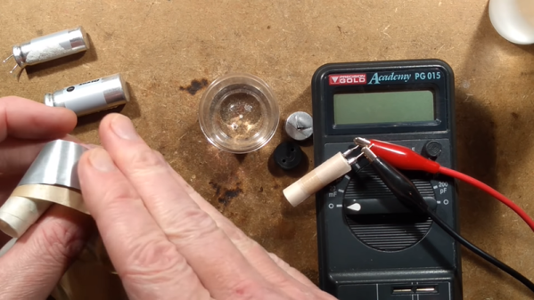
To be fair, [This Does Not Compute] never seems to have really warmed up to destructive removal, so he invested in a pair of hot tweezers for the job, which works really well. But perhaps you’re not sure that you should just reflexively replace old electrolytics on sight. If so, you’re in pretty good company.

Continue reading “Leaky SMD Electrolytics? Try These Brute Force Removal Methods”

Learning About Capacitors By Rolling Your Own Electrolytics

Ever wonder what’s inside an electrolytic capacitor? Many of us don’t, having had at least a partial glimpse inside after failure of the cap due to old age or crossed polarity. The rest of us will have to rely on this behind-the-scenes demo to find out what’s inside those little aluminum cans.

Perhaps unsurprisingly, it’s more aluminum, at least for the electrolytics [Denki Otaku] rolled himself at the Nippon Chemi-Con R&D labs. Interestingly, both the anode and cathode start as identical strips of aluminum foil preprocessed with proprietary solutions to remove any oils and existing oxide layers. The strips then undergo electrolytic acid etching to create pits to greatly increase their surface area. The anode strips then get anodized in a solution of ammonium adipate, an organic acid that creates a thin aluminum oxide layer on the strip. It’s this oxide layer that actually acts as the dielectric in electrolytic capacitors, not the paper separator between the anode and cathode strips.

Winding the foils together with the paper separator is pretty straightforward, but there are some neat tricks even at the non-production level demonstrated here. Attachment of lead wires to the foil is through a punch and crimp operation, and winding the paper-foil sandwich is actually quite fussy, at least when done manually. No details are given on the composition of the electrolyte other than it contains a solvent and an organic acid. [Denki] took this as an invitation to bring along his own electrolyte: a bottle of Coke. The little jelly rolls get impregnated with electrolyte under vacuum, put into aluminum cans, crimped closed, and covered with a heat-shrink sleeve. Under test, [Denki]’s hand-rolled caps performed very well. Even the Coke-filled caps more or less hit the spec on capacitance; sadly, their ESR was way out of whack compared to the conventional electrolyte.

There are plenty more details in the video below, although you’ll have to pardon the AI voiceover as it tries to decide how to say words like “anode” and “dielectric”; it’s a small price to pay for such an interesting video. It’s a much-appreciated look at an area of the industry that few of us get to see in detail.

Continue reading “Learning About Capacitors By Rolling Your Own Electrolytics”

Fix Old Caps, But Keep That “Can Capacitor” Look

Vintage electronics and capacitor replacements tend to go hand-in-hand. Why? Because electrolytic capacitors just don’t last, not the way most other components do, anyway.

The metal terminal ring and the central plate are kept for re-use, and the metal case re-crimped after the internals of the capacitor are replaced with a modern equivalent.

It’s one thing to swap old caps with modern replacements, but what about electronics where the components are not hidden away, and are an important part of the equipment’s look? [lens42] shares a method for replacing antique can-style capacitors in a way that leaves them looking completely original. All it takes is some careful application of technique.

The first thing to do is carefully file away the crimp of the metal can until one can release the ring and plate that hold the terminals. Once that is off, the internals can be pulled from the metal can for disposal. Since the insides of the old cap won’t be re-used, [lens42] recommends simply drilling a hole, screwing in a lag bolt to use as a handle, and pulling everything out. There’s now plenty of space inside the old can to hold modern replacements for the capacitor, and one can even re-use the original terminals.

That leaves the job of re-crimping the old can around the terminal ring to restore a factory-made appearance. To best do this, [lens42] created a tapered collar. Gently hammering the can forces the bottom into the taper, and the opening gradually crimps around the terminal ring. It’s also possible to carefully hammer the flange directly, but the finish won’t be as nice. This new crimp job may not look exactly the same as before, but once the cap is re-installed into the original equipment, it won’t be possible to tell it has been modified in any way.

If this sounds a bit intimidating, don’t worry. [lens42] provides plenty of pictures. And if this kind of thing is up your alley, you may want to check out the Caps Wiki, an effort to centralize and share details about tech repair, especially for vintage electronics.

Unrolling The Mystery Inside An Aluminum Electrolytic Capacitor

When we remove the enclosure of modern electronics, we see a lot of little silvery cylinders wrapped with heat shrink plastic. These aluminum electrolytic capacitors are common residents on circuit boards. We may have cut one open to satisfy our curiosity of what’s inside, but that doesn’t necessarily mean we understood everything we saw. For a more detailed guided tour, follow [TubeTime]’s informative illustrated Twitter thread.

Electronics beginners are taught the basic canonical capacitor: two metal plates and an insulator separating them. This is enough to understand the theory of capacitor operation, but there were hints the real world is not quite that simple. We don’t even need to disassemble an electrolytic capacitor to get our first hint: these cylinders have markings to indicate polarity, differentiating them from the basic capacitor which is symmetric and indifferent to polarity. Once taken apart and unrolled, we would find two thin aluminum foils separated by a sheet of paper. It would be tempting to decide the foil were our two plates and the paper is our insulator, except for the fact those two metal plates are different sizes further deviating from the basic capacitor.

Electronics veterans know the conductor–insulator–conductor pattern is not foil–paper–foil, but actually foil–oxide–electrolyte. But there is more to [TubeTime]’s tour than this answer, which includes pictures of industrial machinery, a side adventure in electrolytic chemistry using a tiny glass beaker, concluding with links to more information. And once armed with knowledge, we can better understand why electrolytic capacitors don’t necessarily need to be replaced in old equipment and appreciate them within the larger history of capacitors context.

Top Off A Dry Electrolytic

Making a capacitor is pretty easy. Just get two conductors close together. The bigger area you can get and the closer you can get them, the bigger the capacitor you can make. [BigClive] found some fake capacitors that were supposed to be very high value, but weren’t. Taking them apart revealed the capacitors didn’t have the electrolyte inside that gives these units both their name and their high values. What did he do? Mixed up some electrolyte and filled them back up to see what would happen. You can see the video below.

Electrolytic capacitors have a secret weapon to get the two electrodes as close as possible to each other. The electrolyte forms a very thin insulating layer on one electrode and the capacitance is between the conductive fluid and that electrode — not between the two electrodes. This allows for a very narrow gap between the conductors and explains why a small electrolytic can have a much greater capacitance than most other technologies in similar form factors.

Continue reading “Top Off A Dry Electrolytic”