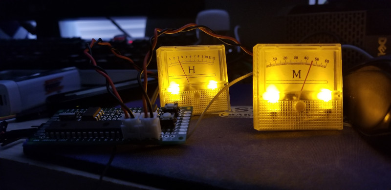
Clocks with hands that turn are all well and good for the common folk, but hacker types prefer something different. [Sjm4306] is one such person, and developed this analog dial clock with parts we’d almost consider retro by modern standards.
The microcontroller at the heart of the build is a PIC16F886. An 8-bit micro from the Microchip brand, it features no Arduino bootloader or USB interface, being flashed via a dedicated programmer. This is combined with a DS1302 real-time clock to keep accurate time, and a MCP4922 DAC which is responsible for generating the output to drive the dials. The dials themselves are sourced from eBay, being simple voltmeters. They’re given a new backing to display hours and minutes instead of volts, and backlit with LEDs for style.
In this day and age, we’re more used to seeing high-end micros used with integrated DACs and USB programming, but it’s nice to see the parts of yesteryear being used, too. It’s not the first clock we’ve seen from [sjm4306], either. Video after the break.


The 16F886 is where I took refuge when the F84 begun to become cumbersome to source.
Sometimes I don’t know why arduino gets called modern and pics retro. You can get a 12f675 which will run at 4mHz with zero external components for under a buck and 18f27 which will run at 64mHz with zero external components for a buck fifty. They both have 4 times the memory of the uno/nano thanks to no bootloader, and they can do a 12 bit analog conversion in 31ns instead of 100000ns. Smh.
Ok. What is the added value of this hackaday.io page over just the youtube video? Really curious. I still have a very big round milliamp meter lying around for a project like this. Time…
Mostly nothing.
But should he want to make a follow up video then this would be cleaner/clearer than a YouTube playlist.
Should he want to add additional text posts or resources the io page is far superior.
Should he want to engage with commenters that too can all be done in one place.
IMO it’s why github was a revolution versus raw git, svn and hg.
I far as I know it was developed to give a long lasting and formalised structure to projects which were previously hosted on short lived probably domicile hosted websites.
If you have a single meter you could alternate between hours and minutes displayed every few seconds. To make reading easier you could use light colors with corresponding face marking colors to make the face readout appear to change in a retro fashion (red markings disappear in red light, blue Markings disappear in blue light). Darn that lack of time!
Nice project! It could look pretty retro with the meters in an old piece of equipment that had two analog meters.
Has anyone done something similar with a DMM? Have the micro output a voltage such as 12.30v for 12:30 etc. Or 1.230v if you were willing to modify the DMM.
You can’t easily modify multimeters as they use a chip that does everything and their LCD do not have separate controllers. If you make a programmable power suppky high resolution DAC, you can drive any voltages you like to the DMM.
So it would be interesting if the DMM were the digital display for an analog circuit. A 1-hour long ramp from 0 to .59 volts, and a circuit that steps in integer volts from 1 to 12 that is added to that.
Sure, but any error in the hour clock will offset the minute clock as well, so it’s going to be a challenge.
In terms of bits, you need to produce an accurate linear voltage ramp with a millivolt resolution up to 12 volts, and less than 0.5 mV of temperature drift, which means you need a 12 bit DAC with a low noise floor. I’m willing to bet your DMM isn’t that accurate either.
Table look up can fix non-linearity. Better than 0.5mV drift over 12V is about 41ppm which isn’t impossible if you know what you are doing. The crappy DS1302 RTC can easily be +/-50ppm for an external crystal without proper calibration and then there is temperature drift. :P
It wasn’t about the clock drift, but the DAC drift.
But there’s an annoying habit with these cheap plastic panel meters: they’re affected by static electricity because the needle has to be so light and delicately balanced to work with microamps of current. They’re not that accurate in and of themselves without closed loop control.
For moving coil, it really doesn’t matter much as the resolution is not that great – not like you have a Vernier scale or something so you won’t be able to tell anyways.
For DMM, you can do ratiometric by using *same* voltage reference for the DAC and the DMM. Same reference, so drifts are in the same direction for the same amount. Older designs uses a floating ground as negative terminal, so just have to be aware of that.
For static in a DMM, it is a matter of a aluminized mylar shield inside the DMM hooked up to the ground. My first DMM (+/-0.25%) has that. There is a +/-0.1% model using same PCB, so it is a solved problem.
BTW noise floor can be lower significantly if you lower the bandwidth. A clock doesn’t need an more than 1 per min updates, ie sub Hz bandwidth. The word you are looking for is drift, non-linearity NOT noise floor.
Almost like groundhog day
https://hackaday.com/2019/01/29/follow-the-bouncing-needles-of-this-analog-meter-clock/
Kinda wish it had a second hand, um I mean meter.
As much as I’m just as nostalgic as everyone else, this whole “let’s just make a retro-themed clock that somehow still isn’t like the 454136516 other ones” thing is getting a bit out of hand. Good on him for getting it working, but I really don’t see the practical appeal…