[Erik van Zijst] has had a long career as a programmer, but lacked an understanding of what was happening at a bare metal level. After building a few logic gates out of transistors to get a feel for electronics, he set out to build a working clock using 74-series logic. Naturally, it was quite the adventure.
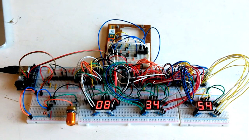
The project starts out as many do on the breadboard. The requisite BCD counters and 7-segment displays were sourced, and everything was connected up with a cavalcade of colorful hookup wires. A 32.768 KHz crystal was pressed into service to generate the clock signal, divided down to get a 1Hz output to drive the seconds counter that would then run the entire clock. [Erik] then had to learn some more practical electronics skills, to deal with debouncing buttons for the time setting circuit.
With the clock now functional, [Erik] decided to take things further, aiming to build something more robust and usable. An automatic brightness control was created using a 555 to run a crude PWM dimmer for the LEDs. Additionally, a PCB was designed to replace the temporary breadboard setup. This led to problems with the oscillator that [Erik] couldn’t quite figure out. Rather than continue on the same path, he changed tack, instead replacing the quartz crystal with a modern MEMS oscillator that solved the problem.
It’s a great look at how to construct a working clock from bare logic, and one that serves to remind us just how complex even a seemingly simple device can be. We’ve seen other from-scratch builds before too, like this 777-transistor clock, or this attractive stacked design. Video after the break.


Cool project. Erik should should hook-up the unused inputs of the 74HCT/74HC chips to ground or Vcc. Without it, it will be spewing RF noise all over the spectrum. (No such need for 74LS).
I see RF noise as one of the lesser problems with floating inputs. Excessive standby current consumption and intermittent failures normally result from this mistake.
Indeed, but those don’t affect other systems :-)
> Erik should should hook-up the unused inputs of the 74HCT/74HC chips to ground or Vcc.
Yeah, the unused inputs of the 74HC74 are indeed tied up to ground for this reason (as are unused inputs elsewhere on the board).
Yeah, the unused inputs of the 74HC74 and all other components are indeed tied to the ground plane for that reason. Nothing should be floating (unless I overlooked something?).
Somewhere in the world a Ham radio operator sheds a tear.
The crystal reference diagram he has is for a MHz range crystal not a crystal in the kHz range.
The values of 10M ohm and 22pF are respectively too high and too low for this frequency. A better choice would have been 10k ohm and 22nF (0.022uF).
Even better would be a two inverter oscillator or just an oscillator block.
[Rob] is incorrect in both cases. The circuit is for a crystal oscillator not a RC oscillator.
In general, you use lower feedback values for *high* frequency crystal oscillators. The cap values are also wrong. They should be tens of pF. Always read the crystal datasheet and app notes as the specify the values for the correct frequency.
FYI: TI app note for 32kHz oscillator. https://www.ti.com/lit/an/slaa322d/slaa322d.pdf
Your app note is for a low power pierce oscillator for use with a micro controller. This is completely different.
Most microcontrollers have configurable internal circuitry for the oscillator that allows you to choose: external clock, RC/Cermet, low power crystal, high power crystal.
In this article he is just using one CMOS inverter.
This configuration is unstable at lower frequencies which he clearly discovered.
The “low power pierce oscillator” uses just that: a single CMOS inverter.
A two inverter oscillator is possible as an RC oscillator, but not used for a crystal. (Except perhaps in very exotic applications).
A ready made oscillator is obviously always an alternative, if somebody is not able to do it himself. But you could also just do it right yourself.
A 32kHz watch crystal is normally designed for very low power (operation from a watch cell). It has a high resonance impedance in the >10k Ohm range compared to the 50 to 100 ohms of a MHz crystal.
A crystal also can get unstable if the drive level is wrong, often too high. In that case you need a series resistance to the crystal. That is a major difference of 5V CMOS to modern microcontroller oscillators. The latter are often power controlled and run with the lower core voltage (1,25 to 1,8V). In that case you do not have to fear a too high drive level.
You also have to take care to avoid electrical influence (capacitive coupling) from other parts of the circuitry. That will it also make unstable.
This appnote really seems very good, especially the layout hints. A bad layout can easily lead to unstable operation.
22nF at the crystal? That is a guarantee for a non-functioning oscillator. You are right: Stay with the oscillator block, if you do not understand crystals.
I’m using a phone here and miss read the diagram but there are things that are not obvious here.
A 31.768 kHz is a tuning fork oscillator and different to a higher frequency crystal. It’s very low power and fragile. That is why you have to choose low power xtal mode with microcontroller.
While the symbol on a microcontroller block diagram may show a simple inverter for the crystal drive, I can assure you the actual circuit is s lot more complex.
One circuit example given uses a specific CMOS inverter that is specifically suited to oscillator drive. The CMOS inverters used in this project have different properties.
Cheap and readily available 1second pulse source: kitchen clock. Remove the small IC board, and use the motor connections for the pulse. Memory fails me if a resistor was needed as a load.
Using the 1pps output on a GPS/GLONASS/etc rx would give you your 1hz signal, as well as sync the start second properly.