When you’re looking to add some wireless functionality to a project, there are no shortage of options. You really don’t need to know much of the technical details to make use of the more well-documented modules, especially if you just need to get something working quickly. On the other hand, maybe you’ve gotten to the point where you want to know how these things actually work, or maybe you’re curious about that cheap RF module on AliExpress. Especially in the frequency bands below 1 GHz, you might find yourself interfacing with a module at really low level, where you might be tuning modulation parameters. The following overview should give you enough of an understanding about the basics of RF modulation to select the appropriate hardware for your next project.
Three of the most common digital modulation schemes you’ll see in specifications are Frequency Shift Keying (FSK), Amplitude Shift Keying (ASK), and LoRa (Long Range). To wrap my mechanically inclined brain around some concepts, I found that thinking of RF modulation in terms of pitches produced by a musical instrument made it more intuitive.
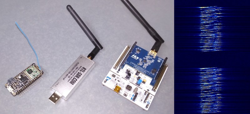
And lots of pretty graphs don’t hurt either. Signals from two different RF dev boards were captured and turned into waterfall and FFT plots using a $20 RTL-SDR dongle. Although not needed for wireless experimentation, the RTL-SDR is an extremely handy debugging tool, even to just check if a module is actually transmitting.
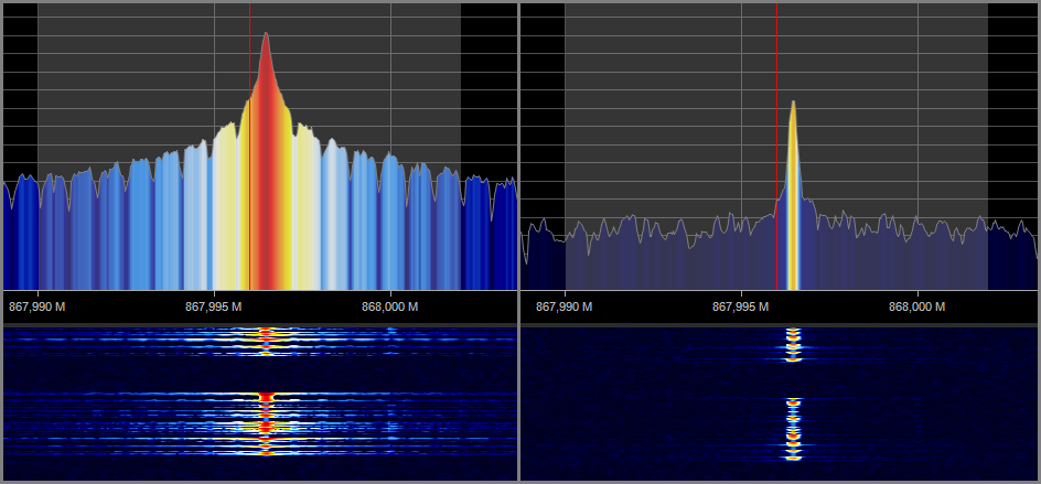
Amplitude Shift Keying
As the name suggests, with Amplitude Shift Keying the amplitude is shifted between two levels, like playing a single note (frequency) on a piano loudly or softly, to represent binary data. ASK modulation’s main advantage lies in its simplicity, which allows for very cheap hardware. It is also very bandwidth-efficient since it only outputs on a narrow frequency band. However, ASK modulation is badly affected by interference, which limits its effective range. A simplified form of ASK modulation is On-Off Shift Keying (OOK), where the transmitter is simply switched on (1) and off (0). This has a power saving advantage since no power is emitted for a 0 symbol. ASK is often used in cheap RF remote controls for consumer devices and automatic garage doors. RF modules that support more complex modulation schemes often can also do ASK and OOK modulation.
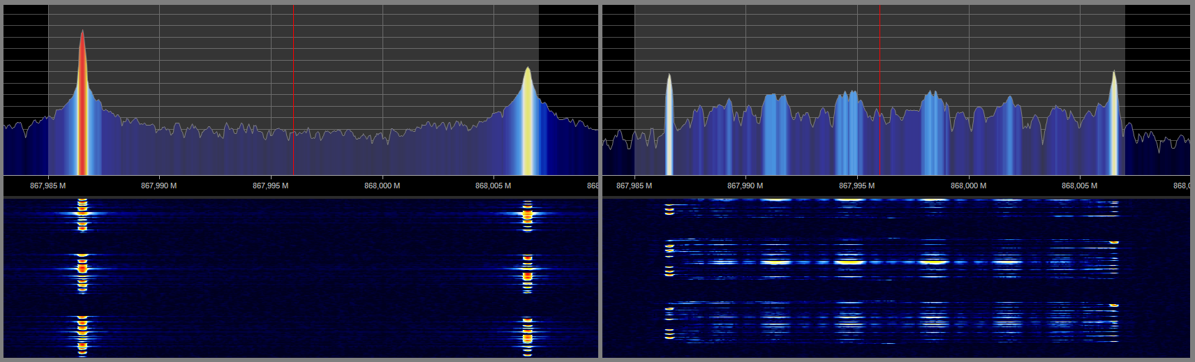
Frequency Shift Keying
In Frequency Shift Keying the transmitted signal shifts between two different frequencies to represent binary data, like two different notes from a piano. This would technically be 2-FSK modulation. Four different frequencies can also be used (4-FSK) to represent 01, 11, 10 and 00. FSK uses more bandwidth, but is less susceptible to interference than ASK, allowing for a much longer effective range up to multiple kilometres. On real hardware, the rapid frequency changes can cause the desired frequency to be “overshot”, creating interference. To solve this, a common variation on FSK is Gaussian FSK, where the shifts between frequencies are smoothed to help reduce the effective bandwidth of the signal. Bluetooth Low Energy uses GFSK modulation.
LoRa
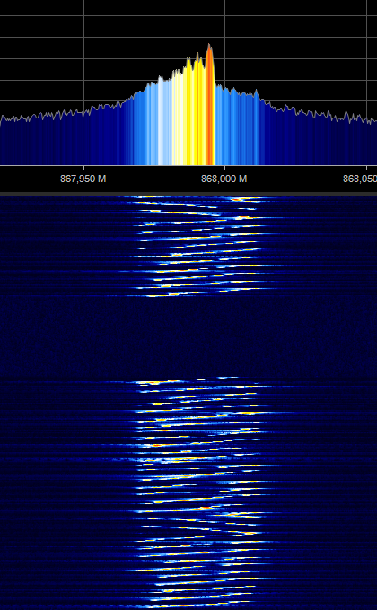
The current darling for long range applications is LoRa, which most Hackaday readers would have heard of many times. LoRa is a form of “chirp spread spectrum” modulation. The “chirp” signal sweeps smoothly across specific frequency range: usually 125 kHz, 250 kHz or 500 kHz wide. How long the sweep takes to complete is determined by the “spreading factor” (SF). The SF is between 7 and 12, which is equal to the number of bits encoded in each chirp. A higher spreading factor reduces the data rate, and increases power consumption, but also makes it easier for the receiver to distinguish the signal from background noise, and helps with longer-range transmissions. Data is encoded by shifting the start frequency of the sweep. When the sweep reaches the end of the top frequency, it “rolls over” and start again from the bottom frequency.
LoRa modulation allows for good receiver sensitivity and interference immunity, but it comes at the cost of bandwidth efficiency. Another disadvantage is the higher cost of hardware, partly due to the patent on LoRa modulation. All manufacturers of LoRa RF chips must pay license fees to the patent holder, Semtech.
Closing Transmission
When working with RF, it’s always a good idea to know what your local regulations are with regard to allowed frequencies and output power. You don’t want authorities knocking on your door for jamming everyone in the neighbourhood’s key fobs. If you stay within the ISM bands, usually 868/915 MHz and 2.4GHz, licensing isn’t required. However, you can always get your ham radio license, and access more of the frequency spectrum, at much higher power output to even achieve intercontinental communications.
The modulation schemes above are only some many in existence, each with advantages and disadvantages. You’ll probably end up with a few choices in your parts inventory, so don’t be afraid to play around with them for different use cases. And be sure to pull out an SDR dongle and have a look!


Nice summary, thanks for posting :-)
Nice
As person not formally trained in RF but who had to learn to make low power ISM band radios work in very non-optimal use cases in battery powered bespoke designs where the battery size was limited and not field replaceable, I found the following to be good rules of thumb.
All other variables being equal. I.e. power use, device size, antenna size and configuration, lack of in-use environment control, time constrained reliability of comm channel, etc.
1. The higher the carrier frequency, the lower the effective range
2. The higher the bit rate, at any carrier frequency, the lower the effective range.
3. Antennas designed specifically for your use case in small devices will increase your effective range.
4. Antenna design is black art best left to wizards
5. Use an RF engineer to layout your boards. A poor layout will de-tune your radio.
6. Diversity antennas will help decrease nasty multi-path signal drop outs
7. A bespoke protocol designed for your use case that minimizes radio on time, TX power and traffic will make your battery last longer vs some standard stack. Every bit you send uses battery optimize to conserve battery.
8. Frequency diversity will help minimize interference. A bespoke frequency diversity design vs standard frequency hoping protocol can minimize the power used to re-synchronize the radios especially when the transmission duty cycle is very low and the transmission duration very short.
9. Choose a good integrated radio chip . If possible have an RF engineer to benchmark the candidates.
10. Build-in OTA firmware update capability to prevent returns to factory for S/W bug fixes.
11. Use good batteries, Tadiran Primary lithium-thionyl chloride. to insure consistent long life performance. Not crap Chinese
Using the principles above I was able to design devices that would work in the field for at least 3 years on 1500 mah primary lithium batteries sending ack/nak signals an average of 3 times a minute
“The higher the carrier frequency, the lower the effective range”
This, combined with:
“All other variables being equal. (I.e.) [..] antenna size”
isn’t actually true. You need to keep the antenna *gain* the same, not the size, which means the antenna shrinks proportionally as you increase the frequency. Look at how Friis originally derived the transmission formula: it’s (area*area) divided by wavelength squared – which means as you increase the frequency (decrease the wavelength) the received power goes *up*.
The *modern* formula recasts that as “transmit gain*receive gain*wavelength squared” which means as you increase the frequency (and keep the *gain* the same) the received power goes *down*.
The confusion here is because if you keep the size of the antenna the same, it focuses better as the frequency goes up, and so the peak gain goes up. The frequency dependence in the transmission equation comes from diffraction.
Hence the reason why you talk about using lasers for communication, and people say “oh, there’s no (or little) free space loss.” It’s because the frequency is so high that you can focus the beam extremely well.
Plus there’s the issue of matching, of course: if you use a tiny antenna and start with 1 kHz obviously the range will increase as you go up in frequency and you near the resonance of the antenna.
Correct. The issue is that path loss is based on 20 log frequency, therefore as the frequency goes up and the required antenna aperture for a given gain goes down (or gain for a size goes up) the path attenuation goes up 6 dB each time the frequency doubles. With properly designed antennas, high frequency communications on Earth is generally limited more by obstructions, Earth curvature, tropospheric attention and refractivity than anything else. With decent dishes you can routinely communicate on 28 GHz at a distance of 23,500 miles with only 4 watts into 3 foot diameter antennas. Do it all the time. Easy peasy. It’s called geosynchronous VSAT.
Damn…I knew there was a reason I was having trouble with my part 15 body worn watch sized hermetically sealed battery powered device…that three foot directional antenna had some serious off- node coverage problems. I should have gone for easy peasy.
Great overview, with your RTL-SDR displays especially useful!
Suggest you also mention that antenna elevation is essential at UHF for range enhancement !
“LoRa modulation allows for good receiver sensitivity and interference immunity” I think you can prove that the chirp is not “good”, it is the best possible.
What kind of modulation is used in 2.4GHz RC toys (5 buttons) from NIKKO?
They seem to use a proprietary protocol. Schematic and some RF tests are available at the FCC ID site, https://fccid.io/V9Q-94140R24 , but couldn’t find any datasheets for the Rx/Tx chips. The car is called “VaporizR 2”.
There are only two types of modulation:
AM (standing for Ancient Modulation) and
FM ( standing for Freaking Magic)
Phase modulation is a form of FM.
All known modulation formats extend from one or a combination of both of these 2 modulations.
As examples, SSB and 8VSB are both highly filtered versions of AM, PSK and spread spectrum hopping are examples of FM. Most useful modern modulation schemes consist of varying the “carrier” in both amplitude and phase angle simultaneously to permit the use of multiple “positions” of amplitude and phase to represent a transmitted bit thereby using bit compression in the transmitted signal. If up and down is in phase or out of ohase amplitude and left and right is phase shift then Google 32qam constellation patterns for an example.
Most “digital” modulation has multiple bit positions (such as 8 APSK) and also has pre processing to apply additional coding to the data payload which can be used when demodulated to reconstruct the payload in event of a bit loss (called forward error correction or FEC). Spread spectrum such as LoRa or CDMA is also a pre processing function and not really a modulation type.
Although everyone refers to data modulation as digital, all modulation techniques today are very analog and except for the most primitive modulation schemes such as Morse code or PSK use highly linear analog amplifier chains for transmitters or BUCs.
To clarify on the constellation graph distance from the center is amplitude and rotation from 0 at the top is phase.
Wow, excellent article and comments. I am researching FM and AM modulation in life, ie both plants and animals (perhaps microbiological life as well). Chirp modulation is used by bats and whales, elephants probably use Rawleigh waves (by stomping their feet as in earthquake) to FM communicate…how Mother Nature modulates signals may help us understand extraterrestrial life attempts at long range communication!
Chirp => glissando/portamento
“If you stay within the ISM bands, usually 868/915 MHz and 2.4GHz, licensing isn’t required.” To clarify: The ISM bands are “license-free”, but this only means that the end-user doesn’t need a license to operate the equipment. You don’t need a license to use a wifi router in your house, for example. BUT(!) there is still all kinds of licensing you need to do when designing a transmitter! You can’t (legally) just transmit without compliance testing and FCC approval. There are a few (small) exceptions for hobbyists with 5 or fewer devices, but even these have to be designed within the limits set by the FCC.
Can anyone help me decode a UHF FSK signal sent from an S2LP?
I am able to transmit between devices but I have an SDR that I am trying to decode on and finding it impossible!
Any help would be greatly appreciated.