When we use a microcontroller to flip a few GPIOs or talk SPI to a peripheral chip, we are often overlooking that it will usually contain an array of built-in peripherals that were once the preserve of extra hardware. Analogue ports, timers, UARTs, and clock generators, to name just a few. [Giovanni Bernardo] has been experimenting with one of these, the internal frequency synthesiser on many PIC microcontrollers, and he’s produced a handy square wave generator for which he’s placed code on GitHub and produced a write-up (Italian language, Google translate link).
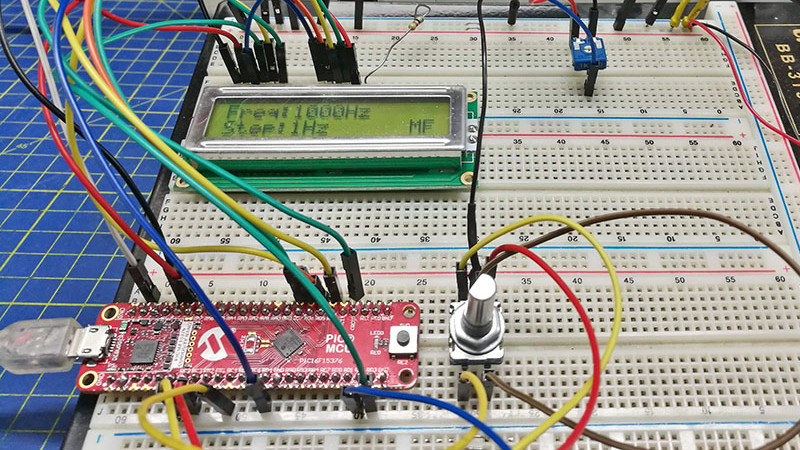
The board used is a PIC16F375 Curiosity Nano, and code takes input from a rotary encoder to set the frequency, with a button to select different step sizes and an alphanumeric LCD display to show the current settings. Frequencies from 1 Hz to 15 MHz are possible, with a clever switch between two of the PICs internal clocks to be used as the reference frequency. Stability depends upon whatever source the PIC uses for its own clock, and while we suspect that will be enough for most users it’s not inconceivable that the PIC could be clocked from a GPS-disciplined source or similar were there a requirement for it.
There are plenty of ways to generate square waves from a microcontroller. Most projects use waveform generator ICs.


Gonna need to see that on a scope, to see how clean or messy the transitions are before I know if it’s useful or not.
You can always add a 7404 inverter to clean up a slightly distorted square wave, I suppose. I’d worry more about the jitter and random glitches in the waveform caused by the software. Also, the author said, “above 10MHz square waves appears weird on the oscilloscope…”, so the absence of a ground plane and impedance-matched output with transmission lines are somewhat the problems as well, but not as much – if one really wants to see a 20 MHz clean square wave with sharp edge like a textbook waveform, the first thing is getting a 200 MHz oscilloscope…
There are likely 2 separate issues:
– The edge rate of the signal is only dependent on the output driver rise/fall time not the output frequency. If you zoom in enough, even a low frequency output would have under/overshoot ring etc. The breadboard, non-controlled loose wires would cause impedance mismatch. Also scope probing should be done with spring ground clip *at* the breakout board itself and not after a long loose wire. A series resistors of around 100R at the breakout point might help if you insists on using breadboards and loose breakout wires.
– For a NCO, essentially the input frequency is essentially its sampling frequency. The NCO keeps track of phase errors, so the *average* frequency over a long time period is correct, but periods of individual cycles can vary. So when you push the frequency high enough, this becomes more pronounced and you would see the output period varies for each cycle.
It’s probably 3 separate issues. “The edge rate of the signal is only dependent on the output driver rise/fall time not the output frequency”, sure, it’s the most important problem if one talks about signal integrity and impedance matching. But what I meant was the superficial appearance of the waveform due to the limited oscilloscope bandwidth. The author was probably using a 100 MHz oscilloscope – In my experience, a good approximation of the square wave requires its fundamental plus four odd harmonic frequencies. For a 10 MHz, 50% duty cycle square wave, it is 90 MHz. No matter how good your impedance is matched, at this point, a 100 MHz oscilloscope starts showing some difficulties on capturing its signal, the higher, the worse. It’s simply impossible to show the waveform like a “textbook”. Also, if you cannot see its > 100 MHz harmonic, you certainly cannot have an accurate picture for the overshoot and ringing, which is in the 500 MHz – GHz range. Historically, to observing high-frequency content, a 1 GHz sampling oscilloscope was a good, low-cost alternative to a real-time oscilloscope, they are only useful for strictly periodic and repetitive waveform, which is still useful for seeing the rise time, overshoot and ringing, but it’s useless for any other digital signals, as a result, nobody makes 1 GHz sampling oscilloscope anymore, the only option is getting a high-speed real time scope, unfortunately.
“500 MHz – GHz range”, oops, I meant 175 MHz – GHz range. Better to correct it, as HAD readers are not known for its forgiveness of typos, me included.
Datasheet: TABLE 37-10: I/O AND CLKOUT TIMING SPECIFICATIONS
IO6* TIOR_SLREN Port I/O rise time, slew rate enabled — 25 — ns VDD = 3.0V
IO7* TIOR_SLRDIS Port I/O rise time, slew rate disabled — 5 — ns VDD = 3.0V
IO8* TIOF_SLREN Port I/O fall time, slew rate enabled — 25 — ns VDD = 3.0V
IO9* TIOF_SLRDIS Port I/O fall time, slew rate disabled — 5 — ns VDD = 3.0V
The part has a 5ns (typ) rise/fall time
FYI:
http://www2.electron.frba.utn.edu.ar/~jcecconi/Bibliografia/06%20-%20Osciloscopios%20de%20Almacenamiento%20Digital/Understanding_Oscilloscope_BW_RiseT_And_Signal_Fidelity.pdf
Minor point …
7404 has asymmetrical rise and fall times.
Better would be 74HCT04 or 74HC04.
HCT is high speed CMOS with TTL voltages.
HC is high speed CMOS with CMOS voltages.
Even better would be one of many line drivers that drive into 50 or 75 ohms.
In this frequency range a 50 ohm driver would suit RG58U cable and is more or less the standard.
It will be as clean as any MCU output. I haven’t looked at the code, but I do know from experience that pic MCU’s can be coded for pwm without jitter. I’ve written a few, personally.
>pic MCU’s can be coded for pwm without jitter
It is actually using the *NCO* to generate the high resolution frequency output. It jiggles the periodsto get at the correct average frequency. There will be cycle to cycle jitters as it doesn’t have a PLL to clean it up.
FYI: PIC16F375 is not a valid part number. Likely it is shorted form of PIC16F15375 that the board maker butchered.
Picture shows PIC16F15375 as you presumed.
Finding a chip that has an NCO is itself no small feat. Are there others?
Microchips seems to have NCO along with a tiny amount of programmable logic for their newer chips these days. Their PIC16F188xx has it.
I meant their PIC series. Forgetting that they acquired AVR and other series too.
Despite the simplicity and flaws, this is a very inexpensive way to go. As mentioned above, a little care in the output circuitry would go a long way to make it better. Thank you.
Hi did you ever look at hackrf project it’s on GitHub please let me know what you think about it