Manufacturers of low-cost 3D printers that use the masked stereolithography (MSLA) process are able to build their machines so cheaply because they’re using repurposed smartphone or tablet LCD panels to mask off the UV backlight. Considering the quality you get out of even the entry-level MSLA resin printers, we certainly aren’t complaining about this bit of thrift. But as [Jan Mrázek] explains in a recent blog post, there’s certainly room for improvement.
The problem is that those repurposed LCD panels are, as you’d expect, color displays. After all, even the bottom of the barrel mobile devices moved away from monochrome displays decades ago. But in this case, that’s not what you really want. Since the printer operates on a single wavelength of light, the color filters inside the LCD are actually absorbing light that could otherwise be curing the resin. So an MSLA printer with a monochrome screen would use less energy and print faster. There’s only one problem: it’s not very easy to find high-resolution monochrome displays in the year 2020.
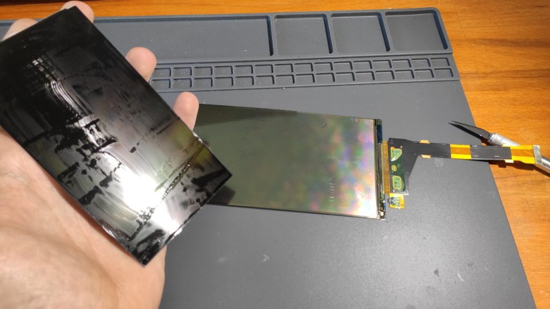
 So [Jan] decided to see if he could take a replacement screen intended for his Elegoo Mars MSLA printer and convert it from color to monochrome by disassembling it and manually removing the color filters. If this sounds a bit crazy, that’s because it is. Turns out taking apart an LCD, modifying its internal layout, and putting it all back together in working order is just as difficult as you’d think.
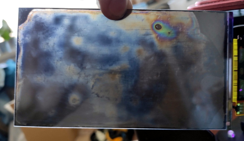
But it was still worth a try. [Jan] pulls the display apart, removes the liquid crystals, scrapes off the color filters, and then puts it all back together again. His first attempt got him a monochrome display that actually worked, but with debris trapped inside the screen, the image was too poor to be useful. He tried again, this time trying harder to keep foreign material out of the crystals. But when he got it back together a second time, he found it no longer functioned. He thinks it’s possible that his attempt to clean up the inside of the display was too aggressive, but really there are so many things that could go wrong here it’s hard to pin down just one.
Long story short, manually creating monochrome displays for low-cost MSLA printers might not be a viable option. Until a better solution comes along, you might be interested in seeing some slightly less invasive ways of improving your resin print quality.


Seems the laser SLA is still the gold standard.
https://theorthocosmos.com/laser-sla-vs-dlp-vs-masked-sla-3d-printing-technology-compared/
could you correct drawings in your paper to match each other ?
(image paste is not supported ;(
what is promoted and oversized is LCD mask
DLP projector’s beam is suggested to start from a single focal point, what is not correct, since the source of beam
is lamp’s light reflected by DLP chip , which is of known size
DLP chip can be flashed with parallel light beam for DLP to work
so your paper is not reliable, since graphics is not reliable
LCD mask has very low transparency 10% vs. 90% in case of DLP (reflected light)
this is the reason, LCD displays with powerful backlight, never flash.
What comes as a gold solution is high resolution array made of leds ( no mask 3D printing technology)
The fact that it worked the first time after this process means it stands a real chance of being a viable path. However, it will likely need machine precision to do the job properly.
Awesome work.
If you just want the result though you can also buy monochrome LCDs made just for this purpose.
https://www.alibaba.com/product-detail/high-resolution-3840×2160-13-3-inch_60757501837.html
That seller got a lot of screens with stripped backlights and polarizer too. (no afil.)
Yup, you are right – there are monochorome screens out there and more are comming. None of them are compatible with the LS055R1SX04, which is used by more than 100k+ existing printers out there. So it would be nice if there would be a manufacturer who will make the compatible screen which is compatible.
And It needs to be compatible :)
Sounds like a job a computer or FPGA could do, slipped in the middle to convert one to the other. Of course that’s easier said than done, but probably easier than getting an LCD factory to do you a custom run for less than 100,000 units.
Looks like they have a 5k model coming.
How about using lasers to remove the color filters? It works for tattoos, mostly without removing the flesh the tattoos are embedded in.
I don’t think it will work. The laser scatters the paint, however you still have to remove the debris. To do so, you still need to split and put back the display – which is the hardest part of the whole process.
Just to add; in case of tattoo removal it works by breaking the pigment particles into smaller ones which cal be collected by the person’s immune system.
Jarvis, fire up the CRISPR, we’re going to give these LCDs an immune system….
It used to be the case that mono displays weren’t TFT, so were more transmissive than colour ones. That was back in the 90s though…
Due to very low 5% UV transmission, LCD looks to be time-waster, since 95% of UV light is lost.
In theory you can use high power wide-beam UV laser but 100W is still a pocket power for a single flash.
So my suggestion is to use old full hd video projector, coming with an array of “mechanical mirrors”.
Replacing standard xenon bulb with UV wide beam laser, only 10% of UV gets lost.
In theory you can design synthetic lens to remove lens made of glass in UV path.
You can get an old video projector with failed bulb at $10 and get fullHD or HD resolution for low cost 3D printing experiments.
Let me know your opinion.
I can donate a number of used video projectors for such project.
That’s already being done, so it’s a good idea. The main problem is it’s more expensive than an LCD. The low transmission doesn’t ultimately stop it working, just makes it much slower.
I don’t know if this is cruel, but stay tuned… I am contemplating a project that involves laser scanning for other purposes. It may be adaptable to this purpose by sticking a UV laser in it.
However, I have frequent personal obstacles which mean projects stall for months at a time. So regard it as pretty much vaporware until it turns up.
Maybe doable since the color filters are normally on the outside of a LCD cell. The liquid crystal is a very thin layer – typically 3um or so that is filled during cell construction. There is a pre-alignment step used to make sure the LC molecules have the proper orientation. Disturbing any of this results in a ruined cell, so don’t try to take the actual cell apart. There are usually a couple layers of polarizers and often a light homogenizing sheet to make the backlight more uniform. All those layers should come off pretty easily. Good luck with it. The processes used are petty sensitive.
DLP should still be far better, no filters, no polarizes. But availability is no as great
Yup. DLP is definitely the way to get more UV light on the print surface.
I can donate used DLP projectors for smart projects ( bulb is down )
DLP chip has great potential, never exploited in DIY projects before.
I need to disable Bulb missing sensor error to make electronics to activate DLP chip and video signal channel processing.
White spots DLP chip should be ok for tests.
Yes a couple of years ago was working on a printer using a projector based on a promise of a suitable projector from a relative. Unfortunately the projector didn’t eventuate and the project was scrapped.
ok, simply guide me.
I can buy a number of DLP projectors tomorrow.
Dismantling to check hardware, sensors, to remove a bulb, test DLP chip, may take the whole day.
Have some resin from stamp shop for tests.
DLP 3D printer may be to quick in printing, requiring us to kep resin cooled, while consuming some IR energy coming with UV light.
Ok, project an be developed within one week.
What next ?
Resin is expensive and some reflected UV light may affect hardening speed in the whole bowl.
So I need to learn more from experienced users first.
Looking for mechanics to sink printed object in the bowl.
Rising resin level is not easy solution due to poor levelling.
so life is full of zasadzkas
There are some cheapish parts on Digikey if you’re willing to get creative with the low resolution DMDs.
DMD: https://www.digikey.com/product-detail/en/texas-instruments/DLP2000AFQC/296-DLP2000AFQC-ND/9354396
Controller: https://www.digikey.com/products/en?mpart=DLPC2607ZVB&v=296
PMIC: https://www.digikey.com/product-detail/en/texas-instruments/DLPA1000YFFT/296-51056-1-ND/9745420
The one I linked is only 640×360 but also has a 7.56 micron mirror pitch so you can probably get away with something akin to a print head carriage for a great resolution. As a bonus it uses a socket for all the actual data pins so you can mount it easier.
Woops, didn’t mean to hit report comment….
DLP is better in which regard?
Amount of light reaching the resin over a set length of time? Yes.
Amount of pixels per dollar for the brand new hardware? No.
Speed that the object is printed at? Maybe, but not with a monochrome LCD, which can get the layer time down to just TWO seconds (* according to some claims). At that speed, the Z-axis speed will greatly exceed the layer time in the process.
DLP is better since UV light gets mirrored, resulting in 90% “transparency”
DLP chip comes with HD or fullHD resolution, so offers better resolution if size of your LCD display is greater one of DLP fullHD chip
DLP supports optics, so printed objects ccan be enlarged, downsized on-the-fly
I can buy used DLP projector at $10 for tests
bulb can be down
DLP supports synthetic lens/ lenses approach, which is hot in astronomy today
what matters and what I see as a main obstacle is the high price of resin
> Speed that the object is printed at? Maybe
Depends on how you do it, this build prints an object in 30 seconds : https://arstechnica.com/gadgets/2020/02/a-new-spin-on-3d-printing-can-produce-an-object-in-seconds/
the video presentation is highly unreliable, since what is claimed and called tomographic technique fails to work in case of 3D printing due to reduced transparency of the already hardened segments, shading 3D pixels behind, not getting UV laser light.
what is hot
is DLP Projector Stereolithography 3D rapid Printer
https://www.youtube.com/watch?v=97ARLiTHjX0
but we don’t love resin
jack
manta103g at gmail
2/2
DLP micro mirrors DLP chip explained
2 great videos follow
How Digital Light Processing (DLP) works
https://www.youtube.com/watch?v=9nb8mM3uEIc
3/3
DLP mirror chip explained in slow video
great
https://www.youtube.com/watch?v=KpatWNi0__o
Your posting reflects an incomplete understanding of the technique being employed in this video.
In reality these objects are not printed all at once….The “film” is exposed in RADIAL LAYERS then the sensitized object is developed in the finishing pass….
https://res.mdpi.com/d_attachment/polymers/polymers-11-01819/article_deploy/polymers-11-01819.pdf
There is NO issue with reduced transparency in previously exposed resin. The system uses a photoinitiator and a photoinhibitor. This allows the resin to be “activated” by exposing the photoinitiator to a wavelength which loosens its molecular structure reducing the inhibition. This effect is temporary. as the energy level of any exposed voxel reduces the structure tightens, blocking the PI from bring triggered. In this….the “entry beams” arent accumulating enough energy to allow the photoinitiator to be triggered. Only the “Target voxels” are exposed to enough CUMULATIVE energy to allow the final “curing pass” to flood the entire build vat….ONLY SOLIDIFYING the regions that have the PhotoInhibitor completely inactive still.
Hope this clarifies your misunderstanding of the mechanism at play
In reality these objects are not printed all at once….The “film” is exposed in RADIAL LAYERS then the sensitized object is developed in the finishing pass….They employ a reversible photoinhibitor that blocks the Photoinitiator from catalysis whenever the inhibitor is insufficiently charged. So the Input beams photosensitivity steadily diminishes as the Target Voxels are pumped from a shifting source. The finishing pass that “materializes” the part simply floods the whole chamber with the right wavelength to develop the region that has sufficiently excited photoinhibitor
Ive tried to post a link and my comment doesnt appear so I assume its being blocked by the automod. Google Dual-Wavelength (UV and Blue) Controlled MDPI for a pdf going into greater detail
Someone said this does not work with 3dprinting but I assume they are just unaware of the actual mechanism employed.
google Dual-Wavelength (UV and Blue) Controlled MDPI
There is a pdf that will explain the process of blocking polymerization with a photoinhibitor that acts on one wavelength so the “trigger” beam at another wavelength only causes the photoinitiator in regions that have been preexposed at the first wavelength to be active. So these objects are built in invisible “radial layers” and then “developed” like a photograph.
While the current demonstration is impressive, and while there is still much work to do to perfect it….it isnt entirely new. The use of intersecting beams in SLA tanks has been pursued previously. While most are familiar with the idea of using two weak beams which only excite the photopolymer at the point of intersection….Using a horizontally sweeping beam to develop voxels sensitized by another wavelength projected from above relaxing the photoinhibition.
you exactly know that “the idea of using two weak beams which only excite the photopolymer at the point of intersection” never worked, since at the light energy at the point of intersection is doubled/ trippled … times only.
Photosensitive resin is sensitive to a single beam of light, passing throught the whole tank.
What you claim to work is pseudo-focus effect, applied in stereolitography in the glass, but single focused beam works better.
I read pdf paper , read your comments, promotion
but video presentation is highly unreliable.
Make more videos and play one in slow motion to let us verify, anything get really 3D printed.
Ideas are great but life is for real.
Single light beam entering the tank makes the closest particles of the resin to harden, shading the rest.
For this reason DLP 3D printing in resin is done layer-by-layer to work.
You claim, you can print the furthest layer first.
I wish you luck
I assume e-Ink displays are not transparent in the segments that aren’t black?
e-Ink displays are basically charged black dust suspended in white oil. When the dust is at the back, you can’t see it through the oil, and when it’s at the front you can’t see the oil through it.
Cool thanks.
yea there’s that, the more reasonable and economical way of doing it, or the OG idea of two tone spheres, which worked … since the late 80’s early 90’s but by the time they dilly dallied with that it was the mid early 2000’s and someone said “shit that aint workin” then flooded the market with the now norm e-ink displays as you discribed, just in time to be completely obsolete
a monochrome low refresh rate would have been a game changer in the decade where they first proposed, digital reprintable newspapers, but FFS that was 1984 on beyond 2000
3 used DLP video projectors offered for 3D resin printing project.
Let me know your interest.
manta103g at gmail
there’s no way for this to ever work. the transparent electrodes are on top of the rgb filters. scrape the filters off and you lose the electrodes too. whatever faint image this guy managed to get would have been from the mangled remains of the traces between the subpixels that the electrodes connect to.
Watching a video of someone tearing apart an LCD tv screen, once they separated the screen from the back lit portion, they used wet papertowels over the filter applied to the screen for a couple hours to remove the filter. This made the screen completely visable. Not sure this makes it workable for a resin use though.
Kyle
I would personally love to just know where I can source these high resolution mono lcds myself