Back in high school, all the serious gearheads used to brag about two things: their drag strip tickets, and their dynamometer reports. The former showed how fast their muscle car could cover a quarter-mile, while the latter was documentation on how much power their carefully crafted machine could deliver. What can I say; gas was cheap and we didn’t have the Internet to distract us.
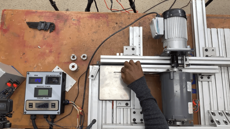
Bragging rights are not exactly what [Jeremy Fielding] has in mind for his DIY dynamometer, nor is getting the particulars on a big Detroit V8 engine. Rather, he wants to characterize small- to medium-sized electric motors, with an eye toward repurposing them for different projects. To do this, he built a simple jig to measure the two parameters needed to calculate the power output of a motor: speed and torque. A magnetic tachometer does the job of measuring the motor’s speed, but torque proved a bit more challenging. The motor under test is coupled to a separate electric braking motor, which spins free when it’s not powered. A lever arm of known length connects to the braking motor on one end while bearing on a digital scale on the other. With the motor under test spun up, the braking motor is gradually powered, which rotates its housing and produces a force on the scale through the lever arm. A little math is all it takes for the mystery motor to reveal its secrets.
[Jeremy]’s videos are always instructional, and the joy he obviously feels at discovery is infectious, so we’re surprised to see that we haven’t featured any of his stuff before. We’ve seen our share of dynos before, though, from the tiny to the computerized to the kind that sometimes blows up.


This is what I typically use… https://www.nxp.com/doc/AN4680
But that won’t get you an equivalent kW rating for continous ussage until you load it…
It should be called the diynamometer
Curious if you could use a torque wrench to measure torque, at least for lower torque values and rpm’s?
No, you need the motor running at speed to measure the HP, you could measure stall torque of something like a servo motor though.
If you know RPM and Hp, torque can be determined. Hp=(Torque*RPM)/5252
You have to know the torque and speed to calculate the horsepower. Horsepower is the result of effort (torque) time and distance. 1 ft lb force applied for 550 feet distance in one minute equals 1 horsepower.
A spring scale works well. You just have to choose one with an appropriate scale.
Outstanding demo and work/thought flow.
I learned a lot!
Pretty neat but some pretty big issues, running DC though a motor like he is doing will quickly overheat the motor without forced air cooling through the motor, over it wont be good enough. Better to use something like a magnetic particle brake than an induction motor.
If he tries to drive the load motor at the speeds he is talking about, like from a universal motor he could actually be in danger. The rotor could birdcage where the rotor expands suddenly as centripetal exceed what it was designed for and all that momentum in the rotor is transferred to the stator and bad things are going to happen. Best case is the torque arm bends and crushes the scale, worst case the cast aluminum bearing mounts break and the motor goes flying.
I watched both videos. You see a clip of him testing a universal motor in the first video at about 19000 rpm. Then he does a followup video where he tested a universal motor at about 20000 rpm several times. Everything performed well and there was no damage or sign of struggle in the setup.
As a side note I agree he should have warned people that motors are balanced at a certain speed and they may or may not have one balanced well enough for that kind of speed.
I would like to discuss this design off-line; could you contact me?