There’s A LEGO Suspension Dyno Now

When it comes to the development and testing of performance suspension, it’s helpful to have a test apparatus that lets you recreate certain conditions reliably. This LEGO suspension dyno does just that, and it’s clearly a big help for those doing R&D on minifig motorcycle suspension.

The build relies on four motors to overcome the resistance of turning a chunky conveyor belt, which acts as a rolling road. As the belt is built out of Technic beams, various LEGO blocks can be added to the conveyor to act as bumps or perturbations for testing suspension.

The video demonstrates the use of the dynamometer, showing how a simple LEGO motorbike design deals with bumps of various sizes. It’s easy to swap out forks and springs and change the geometry to tune the suspension, and the changes can be easily seen when running it through the same test conditions.

While we don’t imagine there are too many people working in this particular field, the lessons being taught here are valuable. This setup allows one to quickly visualize how changing vehicle parameters affects handling. It’s hard to imagine a better teaching tool for vehicle dynamics than something like this that lets you see directly what’s really going on!

Continue reading “There’s A LEGO Suspension Dyno Now”

DIY Prony Dyno Properly Displays Power Production

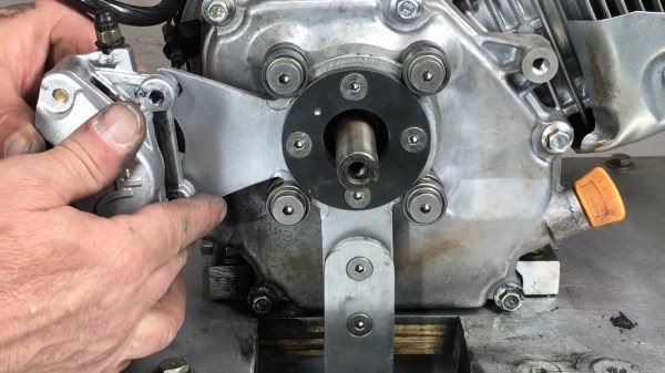
When hackers in the US think of a retailer called Harbor Freight, we usually think of cheap tools, workable but terrible DVM’s, zip ties, and tarps. [Jimbo] over at [Robot Cantina] looked at the 212cc “Predator” engine that they sell and thought “I bet I could power my Honda Insight with that.” And he did, successfully! How much power did the heavily modified engine make? In the video below the break, [Jimbo] takes us through the process of measuring its output using a home built dyno.

The dyno that [Jimbo] has built is a Prony Dyno, and it’s among the oldest and simplest designs available. A torque arm is extended from a disk brake caliper and connects to a force gauge. The engine is ran up to its highest speed, and then he brake is applied to the crankshaft until the engine almost stalls. A tachometer keep track of the RPM, and the force gauge measures the force on the torque arm. Torque is multiplied by RPM and the result is divided by a constant of 5252, and voilà: Horsepower. A computer plots the results across the entire range, and the dyno test is complete.

That only tells part of the story, and the real hack comes when you realize that the dyno stand, the force gauge setup and pretty much everything that can be built at home has been built at home. You’ll also enjoy seeing the results of some driving tests between the 212cc engine and its bigger 420cc brother, how even minor changes to the engine affect the horsepower and torque curves, and how that affects the Honda that he calls his “Street legal go cart.”

Speaking of unusual power plants, how about plant some hobby sized jet turbines on the back of your Tesla for fun?

Continue reading “DIY Prony Dyno Properly Displays Power Production”

Sanity Check Your Engines With This Dynamometer

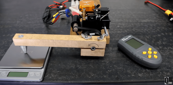
As you get ready to pop the hood of your RC car to drop in a motor upgrade, have you ever wondered how much torque you’re getting from these small devices? Sure, we might just look up the motor specs, but why trust the manufacturer with such matters that you could otherwise measure yourself? [JohnnyQ90] did just that, putting together an at home-rig built almost from a stockpile of off-the-shelf parts.

To dig into the details, [JohnnyQ90] has built himself a Prony Brake Dynamometer. These devices are setup with the motor shaft loosely attached to a lever arm that can push down on a force-measuring device like a scale. With our lever attached, we then power up our motor. By gradually increasing the “snugness” of the motor shaft, we introduce sliding friction that “fights” the motor, and the result is that, at equilibrium, the measured torque is the maximum amount possible for the given speed. Keep turning up that friction and we can stall the motor completely, giving us a measurement of our motor’s stall torque.

Arming yourself with a build like this one can give us a way to check the manufacturer’s ratings against our own, or even get ratings for those “mystery motors” that we pulled out the dumpster. And [JohnnyQ90’s] build is a great reminder on how we can leverage a bit of physics and and a handful of home goods to get some meaningful data.

But it turns out that Prony Brake Dynamometers aren’t the only way of measuring motor torque. For a disc-brake inspired, have a look at this final project. And if you’re looking to go bigger, put two motors head-to-head to with [Jeremy Felding’s] larger scale build.


Continue reading “Sanity Check Your Engines With This Dynamometer”

This DIY Dynamometer Shows Just What A Motor Can Do

Back in high school, all the serious gearheads used to brag about two things: their drag strip tickets, and their dynamometer reports. The former showed how fast their muscle car could cover a quarter-mile, while the latter was documentation on how much power their carefully crafted machine could deliver. What can I say; gas was cheap and we didn’t have the Internet to distract us.

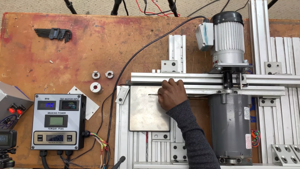
Bragging rights are not exactly what [Jeremy Fielding] has in mind for his DIY dynamometer, nor is getting the particulars on a big Detroit V8 engine. Rather, he wants to characterize small- to medium-sized electric motors, with an eye toward repurposing them for different projects. To do this, he built a simple jig to measure the two parameters needed to calculate the power output of a motor: speed and torque. A magnetic tachometer does the job of measuring the motor’s speed, but torque proved a bit more challenging. The motor under test is coupled to a separate electric braking motor, which spins free when it’s not powered. A lever arm of known length connects to the braking motor on one end while bearing on a digital scale on the other. With the motor under test spun up, the braking motor is gradually powered, which rotates its housing and produces a force on the scale through the lever arm. A little math is all it takes for the mystery motor to reveal its secrets.

[Jeremy]’s videos are always instructional, and the joy he obviously feels at discovery is infectious, so we’re surprised to see that we haven’t featured any of his stuff before. We’ve seen our share of dynos before, though, from the tiny to the computerized to the kind that sometimes blows up.

Continue reading “This DIY Dynamometer Shows Just What A Motor Can Do”

DIY Tiny Dyno

The geared DC motor has become the bread-and-butter of the modern-day beginner project. Unfortunately, with the advent of vast online catalogs peddling a wide assortment of these mechanical marvels, validating the claim that one DC motor will outperform the others is a challenge.

Such is the dilemma that our own [Gerrit Coetzee] faced as he set out to buy these geared motors in bulk. In his initial teardown, he quickly compares the change in design, from the original which possess the two-part clutch that extends on overloading, to the clones with the feature disabled altogether.

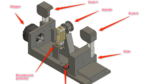
He then goes on to research methods of measuring the motor’s output where he discovers the Prony Brake which leads to the Rope Brake Dynamometer. This is where things get interesting and [Gerrit Coetzee] goes on to hack his own version of the machine. The idea is to have a rope wound to the wheel that is powered by the motor. With one end of the cord attached to a spring scale and the other end to a suspended weight, the motor speed affects the force on the spring scale. This change in force measured by the scale can be used to calculate the power output by the motor.

[Gerrit Coetzee] goes on to replace the weight with springs and the scale with an electronic load cell while using a stepper motor to stretch the cord thereby adding the requisite tension to the string. We thought this was a very elegant solution where the entire experiment could be controlled electronically.

This is a work in progress through the writeup is an excellent example of how to tailor a traditional experiment to the modern times. We have seen similar investigations for larger salvaged motors and dynamometers with lots of sensors.

Motor Test Bench Talks The Torque

Salvaging a beefy motor is one life’s greatest pleasures for a hacker, but, when it comes to using it in a new project, the lack of specs and documentation can be frustrating. [The Post Apocalyptic Inventor] has a seemingly endless stockpile of scavenged motors, and decided to do something about the problem.

Once again applying his talent for junk revival, [TPAI] has spent the last year collecting, reverse-engineering and repairing equipment built in the 1970s, to produce a complete electric motor test setup. Parameters such as stall torque, speed under no load, peak power, and more can all easily be found by use of the restored test equipment. Key operating graphs that would normally only be available in a datasheet can also be produced.

The test setup comprises of a number of magnetic particle brakes, combined power supply and control units, a trio of colossal three-phase dummy loads, and a gorgeously vintage power-factor meter.

Motors are coupled via a piece of rubber to a magnetic particle brake. The rubber contains six magnets spaced around its edge, which, combined with a hall sensor,  are used to calculate the motor’s rotational speed. When power is applied to the coil inside the brake, the now magnetised internal powder causes friction between the rotor and the stator, proportional to the current through the coil. In addition to this, the brake can also measure the torque that’s being applied to the motor shaft, which allows the control units to regulate the brake either by speed or torque. An Arduino slurps data from these control units, allowing characteristics to be easily graphed.

If you’re looking for more dynamometer action, last year we featured this neatly designed unit – made by some Cornell students with an impressive level of documentation.

Continue reading “Motor Test Bench Talks The Torque”

A Dynamometer For Measuring Motor Power

If you have ever ventured into the world of motor vehicles you may be familiar with a dynamometer, possibly as a machine to which your vehicle is taken for that all-important printout that gives you bragging rights (or not) when it comes to its ability to lay down rubber. A dynamometer is essentially a variable load for a rotating shaft, something that converts the kinetic energy from the shaft into heat while measuring the power being transferred.

Most of us will never have the chance to peer inside our local dyno, so a term project from a group of Cornell students might be something of interest. They’ve built a dynamometer for characterising small electric motors, and since their work is part of their degree courses, their documentation of it goes into great detail.

Their dynamometer takes the form of a shaft driving a stainless steel disc brake upon which sit a pair of calibers mounted on a fixed shaft that forms a torsion bar. The whole is mounted in a sturdy stainless steel chassis, and is studded with sensors, a brace of strain gauges and a slotted disc rotation sensor. It’s not the largest of dynamometers, but you can learn about these devices from their work just as they have.

This is a project sent to us by [Bruce Land], one of many from his students that have found their way to these pages. His lectures on microcontrollers are very much worth a look.