[Harry] dropped us a note to let us know about his completed CMOS clock project, and we’re delighted that he did because it’s gorgeous. It’s a digital clock satisfyingly assembled entirely from hardware logic, without a single line of code. There are three main parts to this kind of digital clock: ensuring a stable time base, allowing for setting the time, and turning the counter outputs into a numerical display.
Keeping accurate time is done with a 32.768 kHz crystal, and using CMOS logic to divide that down to a 1 Hz square wave. From there, keeping track of hours and minutes and seconds is mostly a matter of having counters reset and carry at the appropriate times. Setting the clock is done by diverting the 1 Hz signal so that it directly increments either the hours or minutes counter. The counter values are always shown “live” on six 7-segment displays, which makes it all human-readable.
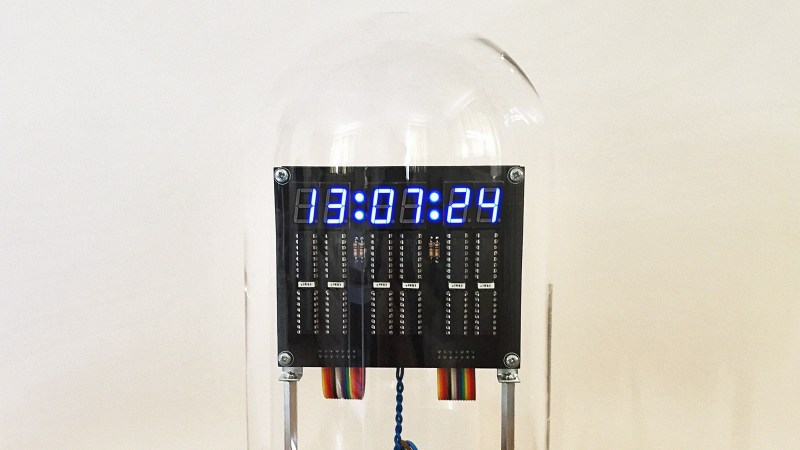
The whole thing is tastefully enclosed in a glass dome which looks great, but [Harry] helpfully warns prospective makers that such things have an unfortunate side effect of being a fingerprint magnet. Schematics and design files are provided for those who want a closer look.
This clock uses a crystal and divider, but there’s another method for keeping accurate time and that’s to base it off the alternating current frequency of power from the grid. Not a bad method, albeit one that depends on being plugged into the wall.


I understand that “To each one his taste” (translated from french), but I fail to see where this is “gorgeous”? How is a black pcb with all that silkscreen, ugly looking parts like the transformer, rainbow colored cables, fuse holder , stand offs and the rest of the components “gorgeous” ?
I disagree, I find the design very pleasing. I like the minimalist “skeleton clock” aesthetic and the tidy build.
If you don’t have anything nice to say then don’t say anything at all.
I’m not sure you do understand “to each their own”. You already said you don’t find it gorgeous, so I’m not sure what answer you could be expecting other than “to you, it isn’t”
I certainly find it very nice looking (but you are not me ;) – the back pcb color doesn’t ‘jump’ and try to take attention, as default green or any fancier color would (except maybe white)
The symmetry of layout and components looks great, at least from the front. Even the transformer seems fitting to have the spot it does, although that did make me presume it used the AC frequency as part of its task.
The back pcb isn’t nearly as nice to look at to me with the same reasons, but no doubt that’s why it is tucked in the back!
Oh yes, this is gorgeous… Unlike humans, with their exposed layer of ugly epidermis and varying levels of visible melanin. And what’s with them adorning them with textiles and trying to enhance them with pigments? I mean seriously, don’t they realize what a fail that is?
Yeah it needs more fake nixies with blue LEDs.
It already has 52 blue LEDs (6*7+6*decimalpoint+2 colons consisting of 2 LEDs each), please do not add more.
But regarding beauty, it is in the eye of the beholder. Personally I see the beauty not in the way it looks, but in the way it is made, how it works. Good to see a project that uses the old-skool style and has the balls to show it with pride. Cool project.
Hehehehe, put neon NE-2 bulbs behind/under the chips, turn that whole blue led under the nixie thing inside out
Because transformers, rainbow colored cables, fuses, capacitors and silkscreens are fucking beautiful, you heathen!
Regular boring CMOS logic? No Arduino? No Frameworks? No IoT?
If a project doesn’t need at least 3 different “lightweight” frameworks, running on a Quad Core PC with 16GB of RAM to communicate to an arudino, it’s just a trivial project.
Where is the web page to set the time?
Where is the web page to set an alarm?
Where are the frameworks? back-end servers, IoT?
Seriously, a nice change on HaD.
You’ll need 8 cores – one for each digits and extra couple to run the GUI and the cloud.
You need a separate Arduino for each digit and another Arduino to keep time on a ds1307, duh.
Right?! Where’s the MQTT? How do I shell into it? You mean there’s no VNC server in there? How’m I supposed to check my social media with it?!
I thought you were gatekeeping hard there for a second, can’t detect sarcasm until after lunch, sorry.
Are there PCBs for sale anywhere? This would be a fun kit.
Building such things with TTL logic was quite the norm in “Introduction to Electronics” (101 or 201) courses in the late 70’s. So this falls under the proverbial, “everything old is new again”. A worthwhile effort, congrats on the outcome.
http://www.rsp-italy.it/Electronics/Magazines/Nuova%20Elettronica/_contents/Nuova%20Elettronica%20045_046.pdf
In the seventies these clocks were sold as kits. In the seventies Texas Instruments sold chips designed to build alar clocks. Now, after this comment I’ll go to search the 45 of Disco Inferno… excuse me…
I only got into electronics a few years ago, and only because microcontrollers let me move much of the complexity from hardware to software. Doing something like might be old, but it boggles the mind of this 45 year old hack!
The idea of making an accurate clock with a display, all in hardware, would literally tie my brain in knots!
It’s all just daisychaining flip flops really.
It is pretty boring: each digits have counter configured for different ranges (6/10/12) + display decoders. As soon as you want additional features, their complexity just blows up in a discrete design. You have a bit of flexibility with a microcontroller.
It’s surprisingly modular. There are discrete IC’s for “Binary coded decimal counters”, and then the counter output goes into a “Binary to 7 Seg decoder” IC. The only slightly tricky part is having the some of the counters reset/overflow at the right digit, which you can do with AND/NOT logic gates.
It’s called “a clock”.
Sorry, should have read:
“The idea of making an accurate clock with a display, all in hardware, would literally tie my brain in knots!”
It’s called “a clock”.
Don’t hurt me, I’m old. I’ll be good.
What would be really cool would be to get one of those domes and put a Raspberry Pi in it.
Hmm, nice, reminds me of my poor efforts as a spotty yoof in the early 70s using scavanged TTL parts from industrial kit my father brought home, though this is far far nicer.
Aesthetically pleasing. 7 segment red LED displays would have been more likely for time period where cost of discrete logic was cheaper than a MCU/ASIC. Assumption to attempt of making appear as antique by glass/wood enclosure. That and blue is irritatingly overused-abused.
Friendly suggestion: Avoid idiota masquerading as authority. Leave it at home and avoid airports/schools.
Single chip clock (e.g. MM5316 in PMOS) arrived in the 70’s and they make it to the $10 digital clock, clock radio. They pack quite a bit of additional functions than you would be able to build with discrete logic chips: alarm + snooze, min/sec display, sleep timer. The period LED was the red and they weren’t as efficient as the ones these days.
The chip made it to 10$ LED clock eventually. VFD was cheaper and brighter but still not 10$. Though the chip itself may have been around that price in one-off 1970s dollars- does seem high. More to 6-8$. MM5314 was more prevalent. No radio supplement on that chip either. If you put it next to your radio it did make some cool Music- of sorts.
For perspective-
Backyard search:
https://hackaday.com/tag/mm5316/
Bad example being Heathkit so naturally more money for the kit. VFD $50 -1977. You have to do a value with your favourite conversion but some where ~200$ todays value (2020).
If you’re talking about the Texas “Cool clock, kid” thing, that kid was clearly hamming it up to get outrage and media attention and it worked
Yes it was the kid (Ahmed) that blew up the non existent bomb, and the situation. No.
That particular situation did get excessive coverage media perversion style due to ethnicity
Sadly it is not an isolated incident.
As to the 60 Hz from the wall… The home I just built is totally PV solar. The clock on the kitchen range loses a couple of minutes per day from the inaccuracies in the pure sine inverter(s).
The clock on our new 2 years ago range isn’t exactly accurate on utility power… and it resets on the slightest millisecond dropout.
Also…
Engineer1: “Do you think we should design extra temperature stability into a device that heats up from room temperature to 200C and drops back again when turned off?”
Engineer2: “Nah.”
I have a 1940s big General Electric wall clock and it’s insanely accurate off of wall current. It has a mechanical indicator to show if the power was lost at any time, I’ve had 1 power outage in the last year that lasted 3 hours according to this clock.
Tell me about that one. The stove clock keeps really perfect time on the power line, but you are right, the slightest little glitch in the line and that one is blinking 12:00. It is a new stove too. I wonder if they have figured out they can use much smaller filter caps and are doing so now. My old microwave rides through the glitches much better. Anybody have a new digital microwave care to comment on how it holds up through power glitches?
The stove is a White-Westinghouse. I have a fairly recent RCA microwave, but never set the time on it, because it’s subject to unplugging if we need to run something else high drain at that end of the kitchen. I would guess though it only resets about a third as often as the stove does.
Thank You for re-living my collage school days.
Learning TTL logic in 1976 and a copy of Don Lancasters book – https://www.tinaja.com/ebooks/TTLCB1.pdf
I built my first TTL clock with Grain Of Wheat Lamps – https://www.amazon.com/Evemodel-Grain-Wheat-Clear-Wired/dp/B01A6B5DYK/
The hours of hand wiring all these parts and the smoke when things were not wired correctly or shorted.
Thank You for all the fond memories. :-)
30+ years I have done it with a 16MHz osc, divided clock rate with a LS93, 5x LS90, feeding 1Hz to bank of 4566 (and a 4011) feed to 4 HP5082-7300 for display. All on 2 piece of breadboard!
My first ever project was like this.
32khz clock crystal to a divider to create a 2hz signal that would go to a binary counter (ignoring the first bit to get 1hz). Using a couple AND gates to handle time logic.
I didn’t go for the extra step of converting to 7-segment though. Just kept it in BCD with leds to make a Binary Clock.
A truly hard core type would just have it blink the LED and stand there and count the blinks. As long as we are talking about clocks that take active user input to read…
There are a couple of Nixie based discrete clocks –
https://www.ebay.ca/itm/Descrete-6-Digit-Nixie-Clock-Board-w-Dekatron-Drive-PCB-Only/153554637682
https://www.shop-tes.com/1384-ti-appnote-clock-pwb/