CherryPi Mechanical Keyboard Warrants A Long Look

[Gosse Adema] has been poking a Microsoft Natural Elite for the last 20 years, and the curvy old girl is about to give out. Looks like he got bit pretty hard by the DIY mechanical keyboard bug in his quest to replace her. Luckily for us, he documented his build.

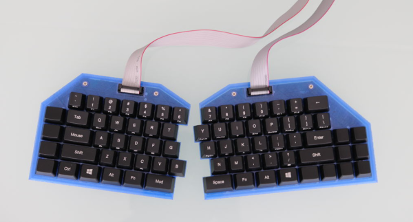
Where do we start? A first keeb is decently-sized undertaking, but [Gosse] turned it up a notch and made it as low-profile as he could — it’s 2cm thick with the keycaps on. This ultimately meant designing the board such that the anti-ghosting diodes sit inside a cutout underneath their respective switches, which are low-profile Cherry MX Reds. There is no Eagle template for those yet, so [Gosse] whipped one up and milled a prototype PCB before deciding to go the fab route.

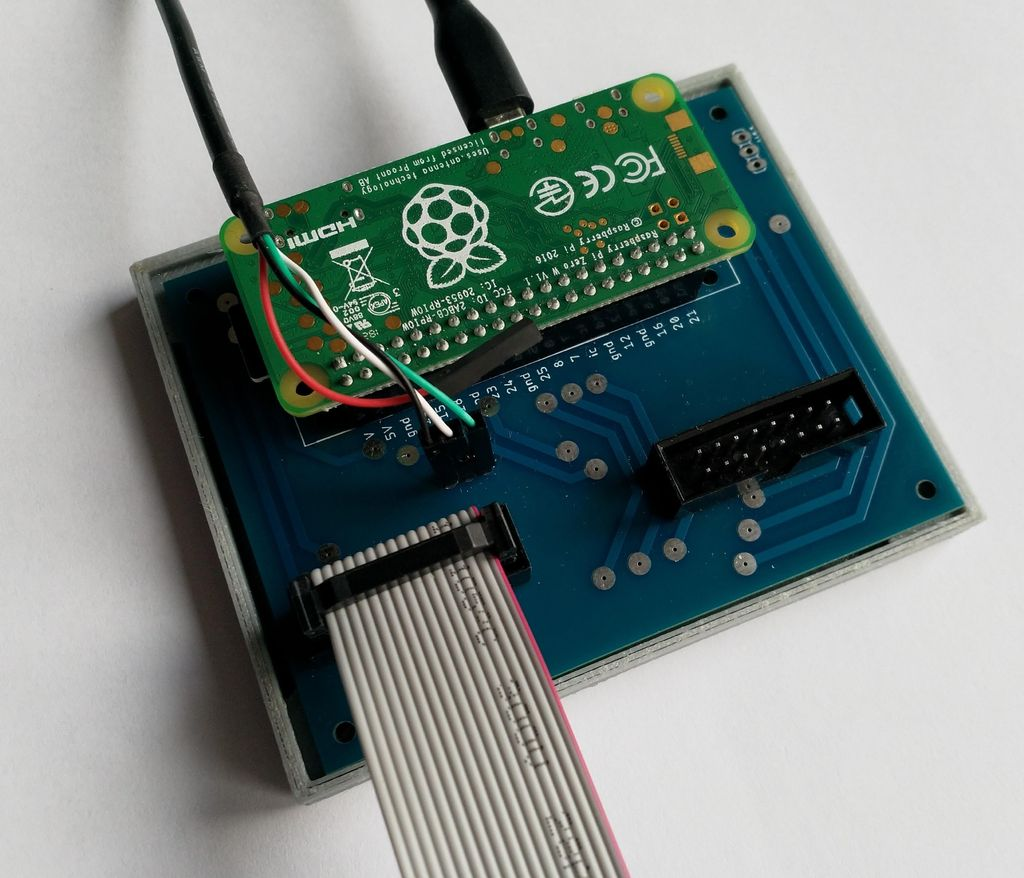
The Raspberry Pi Zero W that controls this keeb lives in a separate controller box in the name of slimness. If you are as-yet unimpressed by this build for some reason, [Gosse] even rolled his own firmware, which he explains as part of this epic journey. Seems the only thing he didn’t do was mold his own keycaps, but not everyone wants to type on blanks. We wonder if [Gosse] is aware of the terrifically low-slung Kailh choc switches, although prefab keycap options for those are even more limited.

Speaking of, here’s a tasty choc-filled game pad.

Procedurally Generating Marble Runs

Marble runs are somehow incredibly soothing to play with and watch, with the gentle clack of the marbles and the smooth, predictable motion. Sadly for some, they never quite got enough time to enjoy them in school. Luckily, [Fernando Jerez] is here with a way to procedurally generate marble runs you can actually play with!

[Fernando] does a great job of explaining the mathematical process of generating the marble runs, using the method of random space filling curves. A maze is drawn on a grid, with points on the grid acting as walls. Each grid cell is then given a value based on points on its corners, and these values then translate into directions of travel. This creates a path through the maze. Scaling this path along the Z-axis, and then replacing the path with a marble track creates the run. It’s then a simple matter of adding a shaft to the loop with a screw to drive marbles back to the top of the run, and you’re all set!

With both animated explanations and actual 3D printed marble runs, [Fernando] demonstrates the concept well. We’d love to print a few runs of our own, and we can’t help but think there’s other great applications for the mathematics behind this concept. If you’re wise to it, drop it in the comments. Otherwise, check out these exquisite creations we’ve featured before!

Lighting Up A Tiny Train Needs Tiny Tools

A tiny toy train that [voidnill] illuminated with a small LED strip fragment demonstrates several challenges that come with both modifying existing products, and working with small things in general. One is that it is hard in general to work around existing design choices and materials when modifying something. The second is that problems are magnified with everything is so small.

[voidnill]’s plentiful photos illustrate everything from drilling out small rivets and tapping the holes for screws to installing a tiny switch, LED strip, and button cells as a power supply. When things are so small, some of the usual solutions don’t apply. For example, cyanoacrylate glue may seem like a good idea for mounting small plastic parts, but CA glue easily wicks into components like the tiny power switch and gums up the insides, rendering it useless.

[voidnill] uses lots of careful cutting and patience to get everything done, and demonstrates the importance of quality tools. The LED strip fragment is driven by three small button cells, and while tape does a serviceable job as a battery holder, [voidnill] believes a 3D printed custom frame for the cells would really do the trick.

The kind of work that goes into making or modifying small things really puts into perspective the amount of effort behind projects like this coffee table with an N-gauge model railway inside it.

Visualizing Energy Fields With A Neon Bulb Array

Everyone knows that one of the coolest things to do with a Tesla coil is to light up neon or fluorescent tubes at a distance. It’s an easy and very visual way to conceptualize how much energy is being pumped out, making it a favorite trick at science museums all over the world. But what would it look like if you took that same concept and increased the resolution? Replace that single large tube with an array of smaller ones. That’s exactly what [Jay Bowles] did in his latest video, and the results are impressive to say the least.

From a hardware standpoint, it doesn’t get much simpler. [Jay] knew from experience that if you bring a small neon indicator close to a Tesla coil, it will start to glow when approximately 80 volts is going through it. The higher the voltage, the brighter the glow. So he took 100 of these little neon bulbs and arranged them in a 10×10 grid on a piece of perfboard. There’s nothing fancy around the backside either, just all the legs wired up in parallel.

When [Jay] brings the device close to his various high-voltage toys, the neon bulbs still glow like they did before. But the trick is, they don’t all glow at the same brightness or time. As the panel is moved around, the user can actually see the shape and relative strength of the field by looking at the “picture” created by the neon bulbs.

The device isn’t just a cool visual either, it has legitimate applications. In the video, [Jay] explains how it allowed him to observe an anomalous energy field that collapsed when he touched the base of his recently completed Tesla coil; an indication that there was a grounding issue. He’s also observed some dead spots while using what he’s come to call his “High-Voltage Lite-Bright” and is interested in hearing possible explanations for what he’s seeing.

We’ve been fans of [Jay] and the impressively produced videos he makes about his high-voltage projects for years now, and we’re always excited when he’s got something new. Most hardware hackers start getting sweaty palms once the meter starts indicating more than about 24 VDC, so we’ve got a lot of respect for anyone who can build this kind of hardware and effectively communicate how it works to others.

Continue reading “Visualizing Energy Fields With A Neon Bulb Array”

Raising The Titanic’s Radio Room

For some reason, of all the ships that have sailed the oceans, it’s the unlucky ones that capture our imagination. Few ships have been as unlucky as the RMS Titanic, sinking as she did on the night of April 15, 1912 after raking across an iceberg on her maiden voyage, and no ship has grabbed as much popular attention as she has.

During her brief life, Titanic was not only the most elegant ship afloat but also the most technologically advanced. She boasted the latest in propulsion and navigation technology and an innovation that had only recently available: a Marconi wireless room, used both for ship-to-shore and ship-to-ship communications.

The radio room of the Titanic landed on the ocean floor with the bow section of the great vessel. The 2.5-mile slow-motion free fall destroyed the structure of the room, but the gear survived relatively intact. And now, more than a century later, there’s an effort afoot to salvage that gear, with an eye toward perhaps restoring it to working condition. It’s a controversial plan, of course, but it is technologically intriguing, and it’s worth taking a look at what’s down there and why we should even bother after all these years.

Continue reading “Raising The Titanic’s Radio Room”

Gorgeous Clock, And Not A Line Of Code In Sight

[Harry] dropped us a note to let us know about his completed CMOS clock project, and we’re delighted that he did because it’s gorgeous. It’s a digital clock satisfyingly assembled entirely from hardware logic, without a single line of code. There are three main parts to this kind of digital clock: ensuring a stable time base, allowing for setting the time, and turning the counter outputs into a numerical display.

Keeping accurate time is done with a 32.768 kHz crystal, and using CMOS logic to divide that down to a 1 Hz square wave. From there, keeping track of hours and minutes and seconds is mostly a matter of having counters reset and carry at the appropriate times. Setting the clock is done by diverting the 1 Hz signal so that it directly increments either the hours or minutes counter. The counter values are always shown “live” on six 7-segment displays, which makes it all human-readable.

The whole thing is tastefully enclosed in a glass dome which looks great, but [Harry] helpfully warns prospective makers that such things have an unfortunate side effect of being a fingerprint magnet. Schematics and design files are provided for those who want a closer look.

This clock uses a crystal and divider, but there’s another method for keeping accurate time and that’s to base it off the alternating current frequency of power from the grid. Not a bad method, albeit one that depends on being plugged into the wall.

Write Once, Run Everywhere: Cross-Platform Programming Done Right

One of the goals of programming languages back in the 1950s was to create a way to write assembly language concepts in an abstract, high-level manner. This would allow the same code to be used across the wildly different system architectures of that era and subsequent decades, requiring only a translator unit (compiler) that would transform the source code into the machine instructions for the target architecture.

Other languages, like BASIC, would use a runtime that provided an even more abstract view of the underlying hardware, yet at the cost of a lot of performance. Although the era of 8-bit home computers is long behind us, the topic of cross-platform development is still highly relevant today, whether one talks about desktop, embedded or server development. Or all of them at the same time.

Let’s take a look at the cross-platform landscape today, shall we?

Continue reading “Write Once, Run Everywhere: Cross-Platform Programming Done Right”