When you measure a voltage, how do you know that your measurement is correct? Because your multimeter says so, of course! But how can you trust your multimeter to give the right reading? Calibration of instruments is something we often trust blindly without really thinking about, but it’s not always an impossible task only for a high-end test lab. [Petteri Aimonen] had enough need for a calibrated current source to have designed his own, and he’s shared the resulting project for all to see.
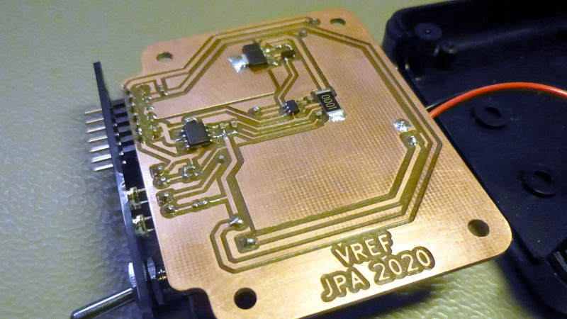
The cost of a reference source goes up with the degree of accuracy required, and can stretch into the many millions of dollars if you are seeking the standards of a national metrology institute, but fortunately [Petteri]’s requirements were considerably more modest. 0.02% accuracy would suffice. An Analog Devices precision voltage reference driving a low-offset op-amp with a driver transistor supplies current to a 0.01% precision resistor, resulting in a reference current source fit for his needs. The reference is available in a range of voltages, his chosen 2.048 volts gave a 2.048 mA current sink with a 100 ohm resistor.
In a way it is a miracle of technology that the cheapest digital multimeter on the market can still have a surprisingly good level of calibration thanks to its on-chip bandgap voltage reference, but it never hurts to have a means to check your instruments. Some of us still rather like analogue multimeters, but beware — calibration at the cheaper end of that market can sometimes be lacking.


Thanks for the reference to a good reference :-) Cheers
In the future I will likely refer back to this reference reference. But for the moment I will defer.
Someone doesn’t know his/her Ohm’s law… :D
Somebody else doesn’t know the very basics of communication.
Ah, voltnut territory. That way lies addiction.
If you have to pick two key specifications of references, they are initial accuracy and drift over time. The latter is usually more of a problem.
Beyond that you consider changes with temperature and humidity, and noise.
And, of course, mechanical stress/shocks causing shifts.
In second paragraph, last line, it’s given 2.048v, 2.048mA and 100Ω. Either the resistance will be 1000Ω or the current will be 20.48mA.
Please read the original article
Which completely agrees with Rudranand, what’s your point Paulo?
Great work! Once again the TI appnotes show their value!
In the “part selection” of its project, [Petteri Aimonen] said :”I chose a 100 ohm 0.01% model, which gives 20.48 mA reference current.”
I’ll just leave this here for the voltnuts:
https://xdevs.com/article/kx-ref/
I’ve been enjoying Marco Reps’ ongoing YouTube saga about building one of these.
I remember doing something similar but the following were different, reference, sink devices, and op-amp. Using an LMP2021 for stability (+-5uV offset max with +-20nV/C) higher Iq but lower min operating voltage (2.2-5.5V versus 4.5-45V). The sink transistor was a single device, (reason, care must be taken not to put too much gain in this type of circuit and less noise), using an FDC637 as the pass transistor.
A nice thing about this type of circuit is the pass transistor handles the max operating voltage not the op-amp. It was operated at 1ma, 5ma, 10ma and 20ma, tested at 16V 10V (10mA max) 5V 3V and 1V. All controlled from a uC it barely made +-0.05%, but was good enough. Also the number of uses for this circuit is kind of large believe it or not.
Not that I have used them recently but I still have a couple Weston cell’s. You kids with your semiconductors… At least this did not have an arduino with flashing blue LED’s back lighting soviet nixie tubes.
Spread ’em, super high precision voltage and current references for all… it will encourage the designing of things where there’s millivolts or microamps between life and death… that should get the population pared down and save us from catastrophe. ;-)
The second I saw the photo I thought a Finnish guy must have laid out that board. I don’t know why, but I just got the feeling and it turned out right.
Do genetics affect board layout style? That’s a thing surely not much studied.