We see a lot of 3D printers here at Hackaday, but as over the years the 3D printer has moved from being an exciting item in its own right to being an everyday tool, it’s increasingly rare for us to feature a build of one as a project. It’s especially rare for us to see a 3D printer that isn’t a variation of either an XYZ Cartesian design or a delta printer, but that’s what [bondus] has done with a printer based upon a parallel SCARA mechanism. If SCARA isn’t something you’re familiar with, it’s a design used in the world of industrial robots in which an almost humanoid jointed arm works in two dimensions, with the third being provided by raising or lowering the whole construction. It has the advantage of greater speed than Cartesian designs, at the expense of higher quality joints being required to maintain accuracy of positioning.
This is the second SCARA printer he’s built, and has a sturdy set of aluminium arms and substantial bearings. Drive comes via a pair of belts to some very large pulleys, and calibration is extremely important to ensure that both arms are in exactly the same plane. The curcular bed is on a lead screw that provides the Z axis.
The results are certainly impressive, both is speed and in print quality. We’ve placed a video of it in action below the break. Whether or not SCARA printers improve to the point of being ubiquitous isn’t something we can supply an answer to, but we’ve featured a small number of them in the past. Particularly memorable is this one using an industrial robotic arm.
Thanks [TechnomadicJim] for the tip.


That is a nice, nimble, large volume 3D printer with a novel concept!
Also, second paragraph, last sentence: “curcular”? circular?
Forgot to add, also rather quiet.
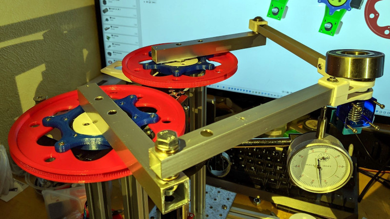
I wonder how little those arms droop, and whether the plate is tilted to compensate.
That big bearing you see on the first picture is used as a weight to check the drop, measured by the dial gauge. Added 180g it dropped 0.15mm. 180g is much more that what the whole arm assembly weights. The square alu profiles used as arms are pretty stiff and light.
Is it… just a 2D Delta XY printer, with a cartesian Z in the end ?
Delta uses 3 actuators simultaneously, SCARA only 2, that’s the key difference here.
And Delta normally referred to linear delta, not arc delta.
At one point I started collecting parts for a Simpson, which was a RepRap design for an arc delta:
https://reprap.org/wiki/Simpson
I have the mechanics of a scara arm here, but could never find a good firmware to controll them. what setup did he use?
That was my experience to.
You can build an entire parallel kinematic using quality normal bearings for less than the cost one linear axis of a cartesian that uses linear rails.
The cost benefit gets even better when you parallel all three axis.
The first stumbling block is finding software to test and optimize mechanical dimensions by examining or mapping out resolution.
Then I tried to use a cheap 8-bit controller – RAMPS.
The work load is too heavy for an 8-Bit, you end up precalculating on a desktop and using lots of tables and this makes it hard to correct for tolerances or calibrate.
You need a better micro-controller but these boards are all quite dedicated and expensive to you loose the cost benefit.
The missing link is a 32-bit driver board that is modular and has a decent programming framework AND is inexpensive. 32-bit micros really don’t cost much more than an 8-bit anymore.
Since all such mechanism have multiple equivalent solutions, you could cross the arms to make it even more compact, or flip just one arm over so it reaches out around the bend.
Not that impressed. There’s a lot of moving mass there, presumably all supported on the stepper motor armature shafts and their bearings. And certain to droop more the further out it is.
At least with a traditional linear XYZ setup or even a Rostock delta there are linear bearings to guide the moving mass with accuracy, and their steppers only have to pull on the printhead assembly and table drive belts.
Nope. The video clearly shows all three axis motors driving via belts. None of the axes are supported by motor bearings.
Wally 3D SCARA printer did this years ago (2013)
https://reprap.org/wiki/Wally
The non-linear nature of Wally’s Z axis really added problems
Youtube video
https://www.youtube.com/watch?v=iVg7WrgHJik
RepRap thread
https://reprap.org/forum/read.php?185,220993
Have Phun
To evaluate this, we need to see the same object printed on a regular gantry style printer as is done on the scara printer. Given equal amounts of time to print, see which produces the greater quality print. My suspicion is that the scara design, like the delta, will have variable resolution, which may also be problematic.
pizza style printer could be done with one linear rail, rotating table, and a Z. which may come in handy around here when they shut dine in restaurants soon.
You can save cost by leaving out the linear tail and use arc or polar like a record player.
For making pizza sure. FDM nah.
The arc of the arm is close to linear anyway.
It’s easy to dismiss the idea with out doing the math.
As I said earlier, this is a barrier. I end up plotting the 3D precision vs accuracy graph in Javascript and render it in a browser.
Cartesian is the best solution for highly rigidity end effectors like milling or routers.
Parallel kinematics with rotational bearings rather than linear rails is far more cost effective for low load end effectors like FDM.
The two barriers are decent software to optimize the mechanical dimensions for a given build volume and low cost modular 16/32 bit driver boards with a development environment more suited to parallel kinematics.
one word -torsion. Not dismissed . At least not casually. I actually have a phonograph and a ‘few’ vinyl records. snickers. Different dynamic.
Trig tables go a long way even on ol 8bit. I prefer to let the more powerful machines to do heavy lifting and dump it to simpler device as well.
Considerable ‘maths’ have been done on polar bots -scara inclusive. I do romanticize long hours of tedious math too. Less Java and browser slow as frozen hell for me tho. Costs do change on what is conceived as a linear actuator and their respective effective implementation. Especially in the apparent need to add ball bearings to everything.
I remember seeing a food printer that had two belts that held a standard kitchen tray. The print head was fixed position.
The belts moving together would move the tray up and down in a space twice it’s diameter.
The belts moving opposite rotated the tray.
There have been several food printers. Cookie /cake decorators my favorites. Pancake printer and Egg shell plotters too.
Nobody mentioning the RepRap Morgan? Pretty sure it was features on hackaday as well a few years ago..
Hi, do you have any plans to release the printer as open source? (or eventually the blueprints for reasonable ammount of money, or to release the printer as a kit )?