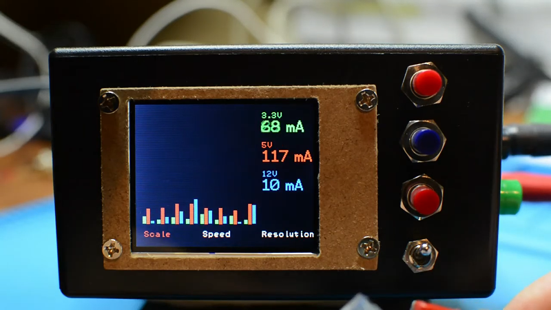
Economy of scale is a wonderful thing, take the switch-mode power supply as an example. Before the rise of the PC, a decent multi-voltage, high current power supply would be pretty expensive. But PCs have meant cheap supplies and sometimes even free as you gut old PCs found in the dumpster. [OneMarcFifty] decided to make a pretty setup for a PC supply that includes a very nice color display with bargraphs and other niceties. You can see the power supply in action in the video below.
The display is a nice TFT driven by an Arduino Nano. The project uses ACS712 current sensor modules, which are nice Hall effect devices that produce a linear output for current and have over 2 KV of voltage isolation.
There are three current sensors, one for each output. Really what makes this impressive compared to many similar projects is the very nice graphical output. The GitHub has all the software as well as PCB layouts. Of course, you’ll have to adapt the enclosure to your specific power supply, but it should be pretty easy to arrange an enclosure.
With only a few buttons, the user interface is a little clunky, but no more so than a lot of other projects. You essentially only use the buttons to change the speed, scale, and resolution of the bar graphs. The output voltages are fixed and there are no current limits.
Another answer is to find a higher voltage supply and mate it with a cheap power supply module. We’ve also seen non-PC power supplies put in a PC case.


“There are no current limits” sounds rather ominous… Author probably wanted to write: “there are no user settable current limits”.
My PC power supply puts out 71A @12V, not enough to start a car but plenty enough to get into big trouble, maybe current limits are a good idea.
At 71A, that is “no current limit” for virtually all purposes.
There is a current limit, it’s when the fire department shows up and cuts power to the house.
Sounds more like a welder than a PC component!
It’s from a.retired 12 core Opteron server with a big disk array
Which has been replaced by a new MacBook Air with more cores and more, faster disk. Oh I love new computers.
Anything can be a fuse, but it’s usually the most expensive component in the circuit.
If you think you can get 10mA resolution using ACS712, you haven’t read the fine prints in the datasheet.
Resolution = Noise/Sensitivity as anything lower is meaningless.
21[mV] / 185 [mV/A] = 0.114A (typ) for a 47nF cap
I once reverse engineered an AT supply. There was in that supply, current limit on the 12V and 5V outputs. I assume that still exists on more modern supplies.
I believe it’s available on up to 30 Amp per rail 12V dual rail PSUs. Server supplies probably assume you’re wired for halon.
The AT supplies, at least, were all built around similar switch-mode regulator chips, and many were just copies of the manufacturer’s applications circuit. However, each design had its own tweaks to the circuitry. I ended up rewiring the transformer outputs to provide 13.8V at something like 30A, which powered a 6M (50MHz) commercial FM transceiver. With overcurrent and overvoltage protection (from the original design).
The conversion was pretty simple, involving reconnection of the transformer’s high current output windings and adjustment of resistive dividers in the feedback to the regulator chip.
Hi chaps, this is marc – I built the thing – thanks for all the interest and the comments! It’s true it does not have a current limitation (when I built this 3 years ago I was more interested in getting the fancy TFT stuff done than anything else ;) ) The next power supply hack project that I will show will be a central POE supply featuring 12V and 48V using an ESP8266 including WIFI and MQTT integration and – yes – it will have 2 relays to cut off (triggered by software, i.e. a 1-100 ms delay. If you subscribe to my channel you’ll get notified when I publish (*selfpromote*) https://studio.youtube.com/channel/UCG5Ph9Mm6UEQLJJ-kGIC2AQ
have fun and stay healthy!
Marc
Doh – got the link wrong – it’s actually https://www.youtube.com/channel/UCG5Ph9Mm6UEQLJJ-kGIC2AQ – sorry…