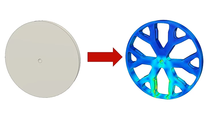
Chairs, spokes on a wheel, bridges, and all kinds of other load-bearing objects are designed such that material is only present where it is needed. There’s a process by which the decisions about how much material to put and where is determined by computer, and illustrating this is [Adam Bender]’s short primer on how to use generative optimization in Autodesk’s Fusion 360 (which offers a variety of free licenses) using a wheel as an example.
 Things start with a solid object and a definition of the structural loads expected. The computer then simulates the force (or forces) involved, and that simulation can be used to define a part that only has material where it’s really needed. The results can be oddly organic looking, and this process has been used to optimize spacebound equipment where every gram counts.
It’s far from an automated process, but it doesn’t look too difficult to navigate the tools for straightforward designs. [Adam] cautions that one should always be mindful of the method of manufacturing when designing the part’s final form, which is always good advice but especially true when making oddball shapes and curves. To see the short process in action, watch the video embedded below.


I am quite concerned about fatigue resistance and unexpected stresses.
In fatigue, small “cracks” develop and advance each cycle. Won’t this designs be less robust as there is less material? It is even worse if we take into account printed structures do not have the same resistance between layers as “pure” material.
The same for unexpected loads: if all possible scenarios are not taken into account (which I believe quite difficult if not impossible) they will fail.
Truly, this design system will optimize some variables but there are inevitable tradeoffs.
There are a number of concerns about optimizing structures. Isotropy is just one of them – behavior after failure is equally important. Think crumple zones in a car.
You can stand on an empty aluminum can, but as soon as you poke the side you’re going down. You can make a box beam out of the fanciest high-strength steel, but once you get a microscopic layer of rust on it, it loses proportionally more strength than the box beam made out of mild steel and three times the material thickness.
Highly optimized, efficient systems are dangerous because they have no play in them.
if it calls for a 2×2, use a 2×4. I’m sure there is some old adage about building things to last. I like to look at school buses as an real life example of overkill. They are the only vehicle on the road built so that the entire passenger compartment may survive if the thing rolls over or gets into a serious accident.
You know how they figured out how to do it? THROUGH A SHIT LOAD OF CRASHES AND ACCIDENTS….
… a process which has NOTHING to do with a bunch of math junkies/programmers sitting around punching buttons.
Even our best ‘simulations’ come nowhere near actually replicating Newtonian physics. Math still cannot describe how a bumble bee can fly, and that is just one example of literally limitless scenarios that we have not discovered, deciphered, and replicated with our silly simple primate brains.
fwiw: I wouldn’t trust fusion 360 as far as I could throw one of the developers. Hell, they can’t even get the thing to run on more than A SINGLE THREAD. The first dual core processors were released in 2005… it’s now 2020. So for fifteen years they have had the opportunity to get multi-threading running properly, and we still have a simple operation hanging up the entire workflow because it simply uses a single thread.
until we actually get good at simulations…. ‘prototype, build, test, try again’ will be our best methodology, as it always has been.
Simulations are much more accurate than your statements here. We don’t need anything magic to know how a bumblebee flies, that’s been known for a long time. If you were to scale one up, it doesn’t work and certainly at those Reynolds numbers, using normal flight equations will not work. School buses cannot survive a rollover, they key here is that they don’t often roll like a car. Instead, it’s usually just a flip to a side which is more survivable.
In case you’re not aware of this, airplanes, automobiles, and buildings have been designed using finite element analysis to simulate loads for over twenty years. And waaaay before that, engineers were designing things based on mathematical models. This has resulted in lighter, stronger structures whose failure modes are quite predictable. The “it broke here: put more metal next time” approach is just Neanderthal. A shit load of simulations trumps a shit load of crashes, unless you value CPU time over lives. Believe it or not, we actually DO understand Newtonian physics. Well, some of us, anyway.
There’s a period in time around 70’s early 80’s where cars turned distinctly angular because they were beginning to design them using CAD on computers that weren’t powerful enough to solve complex geometries.
The Barcelona cathedral was designed upside down…worth reading about.
“Math still cannot describe how a bumble bee can fly, and that is just one example of literally limitless scenarios that we have not discovered, deciphered, and replicated with our silly simple primate brains.”
That’s a myth: they considered only an static scenario, where the bumble bee was gliding with the wings stopped. But when a dynamic scenario, with the wings moving, is considered, it works fine.
But how come the passenger compartment never seems to do that in an accident? Roof ripped off seems to be very common in bus roll-overs. Serious question.
Oddly organic looking? Well that explains biology.
Which speaks well for the process. Organic structures develop and evolve based on where things fail (the shit-load of crashes approach), so if you get a similar result from mathematical modeling and iterative optimization, that’s a good sign.
Actually, organic structures also develop based on removing materials where they aren’t needed. An organism first grows a blob of cells, and then selectively kills cells that aren’t needed to shift their materials to the places where the stresses are causing failures to occur. It’s a constant back and forth.
So it’s a kind of Ford-ism in action. If the seat belt snaps but the belt buckle doesn’t, that means the buckle has too much metal in it.
That was what I meant by “develop and evolve”. Development is what individual organisms do, evolution is what species do.
Optimizations like these are highly dangerous, because of how the problem constraints are set up. For example, here the wheel forces are simulated as a pressure over surface – but this is not what happens with a real wheel. The real wheel is not being squeezed equally around all points – it has a point force spread over the contact patch, so some parts of the wheel are in compression and others are in tension.
Here in the video the guy creates the optimization for one case – the evenly distributed pressure – and then tests it using another case – a point load. This does not establish that the structure is optimal to the case.
Creating a realistic “training case” for the optimizer to find a solution that would actually work can be beyond these simple tools. What you’d really want to do is to run a monte carlo simulation by applying random forces in random directions with certain probability distributions and then find a solution that performs reasonably well in most of them. You get a structure that isn’t strong just for one special case – and what that does is make the structure look more like a traditionally engineered part.
Organic shapes such as bone structures appear because there’s a constant re-modeling of the organism according to what sort of loads they’re experiencing now. Engineered shapes occur because they’re built on what sort of loads they’re expected to carry without failure. A person who lands their foot wrong will get a hairline fracture, and it will heal, whereas a robot foot has to be built to not, because it can’t heal. The organic shapes that you get out of these optimization routines become dangerous because they break like the organic foot, but can’t heal like the organic foot. They just fail outside of their design parameters.
you should do a video on it.
I don’t know these tools well enough to perform a monte-carlo optimization, and it would cost me considerable time and money to get to that level of proficiency. The limitation here from what I’m seeing is that you can’t apply dynamic loads – only static loads that represent dynamic situations. This means something like an oscillating load cannot be placed on the object because it would be represented by two opposing loads that cancel out – or just one load, which leads to an asymmetric solution.
The difficulty in proving an optimization is that you need to know the correct solution, or at least a best solution to compare against. Otherwise, to prove the solution by placing a random load doesn’t show that this is actually better. How do you know a better solution? Well, you have to engineer one. There’s no guarantee that any structure the algorithm comes up with is the best – it is only ever going to be as good as you can judge it to be.
It’s exactly like the problem of trying to develop an AI that is smarter than yourself. In order to do that, you must somehow judge from a position that is smarter than yourself. The practical reality is even worse – you couldn’t even judge an equal intelligence exhaustively to show that it’s not worse in some aspects. This applies to the AI itself as well; you can’t make an AI test an AI to be smarter than the AI… without the ability to differentiate and select, evolution doesn’t work. If you don’t understand the answer, you can’t tell whether it’s better or just cheating your test somehow.
This particular tool is going to make interesting looking shapes that look plausible, but to trust those solutions requires you to know that your training case IS the actual load case and cannot be anything else. It’s rather a tool for coming up with solutions that you already know are correct and you just want to skip the effort of calculating it yourself.
Also, to really prove the solution requires the use of the “Feynman method”.
Which comes form the story where Richard Feynman was sent out to a nuclear testing lab as a consultant for being such a smart guy, to which he wasn’t qualified and couldn’t even read the diagrams, so he just pointed a finger at a symbol…
“So, in order to find out whether it’s a valve or not I take my finger and I put it down in the middle of one of the blueprints on page number 3 and said, ‘What happens if this valve gets stuck?’ figuring they’re going to say, ‘That’s not a valve, sir, that’s a window.’ So one looks at the other and says, ‘Well if that valve gets stuck,’ and they go up and down the blueprint and look at each other and say ‘you’re absolutely right, sir.’ “
He is correct. 20 years of FEA experience tells me so. They are great tools, but I can make the simulation give me the result ‘I want’ even if it doesn’t jive in the real world.
As a former wheel guy, there are lots of other forces in play in a wheel, the obvious side forces when turning, but also the rotating contact pont against the ground will induce oscilating stresses on the spokes, a wheel compresses and springs back continiosly while rolling agains the ground.
There was one manufacturer of car wheels known for developing micro-cracks in the rim (for a special model car), and there was a cheap copy of that rim that worked great, the difference was a few mm thickness of the rim, and the spokes were thicker in towards the car, nothing you could see, and we replaced a lot of the broken OEM’s with the cheap copy.
We also recomending them to go up 5% in profile when changing tyres for a softer ride/more cushioning for the rim
An increase in total diameter does not seem like a good idea, just allows the forces more leverage on the weak bits.
This is classic garbage in garbage out. The pressure load is just one of many loads and a wheel will likely be pressurized and depressurized only tens of times in its life.
More significant is the cyclic radial load applied at the contact patch and the bending load due to cornering. These reverse once per rotation of the wheel.
That style of modelling looks like proving conventional bicycle type spoked wheels impossible, because they hang on the upper half of the spokes more than they stand on the bottom half.
It’s because the model doesn’t account for pre-stressing at all, so it comes to a completely different conclusion about how wheels should be made.
Is anyone else caught up on how Generative Design in Fusion 360 costs 25 credits ($25) per simulation, and then another 100 credits ($100) to get the design out of simulation into model space? Even topology optimization simulations cost credits now, and you can’t run it locally. There are many possibilities to try with gen. design, but the cost is prohibitive and a barrier. Fusion 360 is becoming too greedy – time to hack our own way of doing this.
It was free when the article was written a year ago. Shame it isn’t free now. Makes the article far less worthwhile.
Thank Carl Bass…
The pricing structure, as I understand it is $25 to run your simulation (which can have an unlimited number of iterations and load cases), then $100 to download the specific model you want. It’s not $25 per load case.
For those who don’t trust Autodesk to keep a “free” thing free, FreeCAD has a finite element analysis tool as well. Joko Engineering has produced a number of excellent tutorials on FreeCAD, including this one: https://www.youtube.com/watch?v=dhrynRdBOIg
Does anyone remember the Moties or the Watchmaker sub species? They had this shit down pat….. https://en.wikipedia.org/wiki/The_Mote_in_God%27s_Eye#Moties