You can say one thing for [Derek]’s amateur radio ambitions — he certainly jumps in with both feet. While most hams never even attempt to “shoot the Moon”, he’s building out an Earth-Moon-Earth, or EME, setup which requires this little beauty: a homebrew quarter-wave hardline RF divider, and he’s sharing the build with us.
For background, EME is a propagation technique using our natural satellite as a passive communications satellite. Powerful, directional signals can bounce off the Moon and back down to Earth, potentially putting your signal in range of anyone who has a view of the Moon at that moment. The loss over the approximately 770,000-km path length is substantial, enough so that receiving stations generally use arrays of high-gain Yagi antennas.
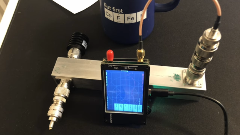
That’s where [Derek]’s hardline build comes in. The divider acts as an impedance transformer and matches two 50-ohm antennas in parallel with the 50-ohm load expected by the transceiver. He built his from extruded aluminum tubing as the outer shield, with a center conductor of brass tubing and air dielectric. He walks through all the calculations; stock size tubing was good enough to get into the ballpark for the correct impedance over a quarter-wavelength section of hardline at the desired 432-MHz, which is in the middle of the 70-cm amateur band. Sadly, though, a scan of the finished product with a NanoVNA revealed that the divider is resonant much further up the band, for reasons unknown.
[Derek] is still diagnosing, and we’ll be keen to see what he comes up with, but for now, at least we’ve learned a bit about homebrew hardlines and EME. Want a bit more information on Moon bounce? We’ve got you covered.


I’ve been learning SimSmith for the past 2 months, so I typed in his circuit to check the calculations.
A 50 ohm generator into a 41.56 ohm transmission line of 90 degrees length into a 25 ohm load does indeed show a minimum SWR at 600 MHz, as he notes.
…and a minimum at 200 MHz as he calculated
…and a minimum at 1000 MHz as well
The SWR plot shows a generally oscillating value with minimums at 200+400*N MHz and maximums at 400*N MHz.
I believe what he’s seeing is the 2nd harmonic of the resonant frequency. If he has the NanoVNA sweep the 200 MHz range (50 MHz to 300 MHz) he should see another minimum around the calculated 200 MHz value.
I put a more detailed description of my SimSmith results up on .IO if anyone wants to check it out:
https://hackaday.io/project/5283-potpourri/log/175349-power-divider-question
There’s some nice plots that show exactly what he is seeing with his constructed version.
Get to it, Jim.
I’m certainly not qualified, and I highly doubt many people here are. Medical devices are far and away from Arduinos and 3D printing.
Damn it Jim, I am a hacker not a medical device manufacturer.
This might just be the best comment I’ve ever seen on HaD.
Excellent Hacking Dan,
73
Dom
M1KTA
As to the topic EME is always great fun, really sparks the imagination, even more than working a satellite or space station repeater. If you are not a ham you can still receive signals, EME was first used to receive electronic intelligence on reflections of Soviet radar installations, it was the first electronic reconnaissance satellite, now I understand that people can pick up and ID the carriers(not decode the picture signal) from big UHF TV stations. That was before the US pacific fleet set up an EME link between Washington and Pearl Harbor in the 50s. Now you work an EME with a good antenna and txing around 100w using WSJT/WSPR to do very slow data.
I would suspect the terminations you have used. One side of port You may have high quality and other side port really poor quality. Put them on your VNA and test both of them. See this article it may qualify the differences you see.
https://www.element14.com/community/groups/test-and-measurement/blog/2018/05/12/which-50-ohm-loads-are-any-good-finding-out-with-the-fpc1500-vector-network-analyzer
Otherwise put some real world loads on it and measure again.
Using a poor load will not make any difference to the frequency of resonance, only to the magnitude of the match, i.e. the deep of the resonance.
Why would you build a tuned cavity power divider like this? I have a 4 way mini circuits I got on eBay for 20 bucks, the loss isnt very high and a good lna on each input is also pretty cheap. So what is the advantage of the cavity design at such low frequency (I’m guessing 900mhz or 1200mhz). It seems to me an investment in some lmr600 feedline and lna’s is a more practical way to keep low loss? I’m actually very curious because I want to build a 1420mhz array that’s why I bought my MC power divider.
If you want to transmit 100mW you can use your mini circuits divider. But if you want to transmit something like 1000W, which you need for EME, your little divider will become a smoking black piece of tar…
Indeed :-)
Ok admittedly I for some reason was only thinking in terms of RX when I wrote that post. But still why not use an LNA in front of a low power transmitter down a good feed line and then put a TX switch and and power amp on each of the dividers outputs? As a poster bellow said RF separates the kids from the adults. I only TX at 2M/40M and this is mostly done for utility in the outdoors on a cheap handie talkie. But I do alot of RX microwave experimentation and I have built my fair share of tuned cavity BPF’s and it’s just not very easy to do, and the times I have done ie its because I cant source a saw filter at that frequency. Like I said im not pushing a mini circuits power divider agenda, just curious about alternate choices to the original solution and the best way to solve the problem with the least error and loss
When we shot the moon (monostatic S band) we used a 300 watt transmitter and a electromechanical RF relay to switch from T to R. Normally we use a 150KW TWT with magnetic/TR tube switching, which works in microsoeconds. But the TWT could only put out 300 usec pulses. We integrated the 300W CW signal for a while to get a signal.
We used a 25 foot parabolic dish. Nice toys. Now all at Wright-Patterson AFB, mostly unused.
Any change made to make production easier of faster for anything in the medical market will have to have agency approval. By the time all the paperwork, testing, and inspection, and certification is done this will all be over. The only design improvements that could be made would be to throw more people into the assembly process. That would require no approvals.:)
Moon Bounce as it was called, was a big deal for a ham when I was a kid, and very exotic. It took a lot of glowing tubes and racks of gear. A ham’s radio shack inside was like NASA mission control before NASA :-)
It would be interesting to see if you could fine tune the impedance by sticking some dielectric inside the tube.
Neat project, never seen square tube used before… though am thinking for directional couplers and modules that’s the situation.
I’ve seen in AM station photos where looks like they use copper pipe like as hard line and have wondered about doing similar with a center conductor for a higher velocity cable/feedline since the LMR400 isn’t cheap. I assume the copper pipes are like a ladder line.
Now I’m thinking to put together a spreadsheet to do the math to see the differences in the cables and the copper pipe and rod method (sucks the household wire that I’m guessing is more cost effective will be a pain to straighten… though maybe a smaller pipe if available straight will do and of course brass rod isn’t as efficient) characteristics and cost.
RF hard line comes in different sizes depending on the power level and frequencies used. 3-1/8 inch coax can be used up to L band (about 1.4 GHz) and a couple hundred kilowatts if you put dry air into it. At lower frequencies (UHF) and higher powers, 8 inch coax gives lower loss. 1-7/8 inch is good for lower loss than flexible coax and reasonable cost. (This stuff is NOT cheap.) There’s also sorta-flexible versions of the coax which mates with hard line, and has a black plastic coating over a corrugated outer pipe.
Inside the coax, the inner pipe is supported by teflon spacers. Flex coax has a spiral of teflon. There are ‘bullet’ connectors which allow joining sections together.
Didn’t think about the air prep to dry.
I guess ideal would be to place Schrader valves and pull a vacuum… probably prep work like for refrigeration lines when soldering also, i.e. nitrogen environment, leak testing, silver solder, etc..
Maybe drop the temperature of the signal path devices can help also like the astronomers do?
Dan, Did you account for the velocity factor of the line?