When the fuel gauge of his 1975 Triumph Spitfire started going off the scale, the collected knowledge of the Internet indicated that [smellsofbikes] needed to replace a faulty voltage regulator behind the dash. For most people, that would be the end of the story. But he, like everyone who’s reading this right now, really wanted to see what the inside of a 45 year old voltage regulator looked like.
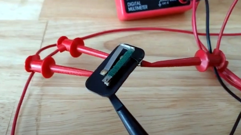
After prying open the metal case, he discovered that not only is the regulator mechanical in nature, but there’s even a tiny screw that allows you to adjust the output voltage. Luckily for us, not only is [smellsofbikes] curious enough to open it up, but he’s also got the tools and knowledge to explain how it works in the video after the break.
 Put simply, the heart of the regulator is a bimetallic strip with a coil of wire wrapped around it. When power from the battery is passed through the coil it acts as a heater, which makes the strip move up and break the connection to the adjustable contact. With the connection broken and the heating coil off the strip rapidly cools, and in doing so returns to its original position and reconnects the heater; thus starting the process over again.
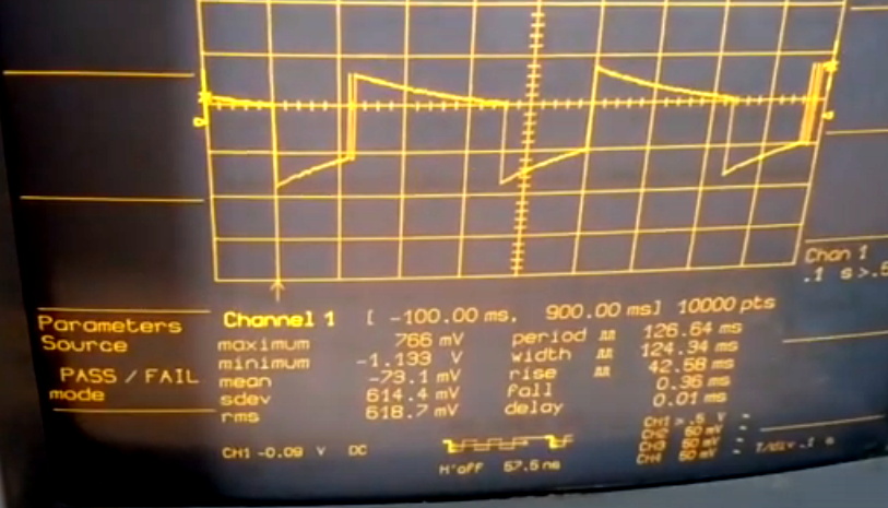
These rapid voltage pulses average out to around 10 VDC, though [smellsofbikes] notes that you can’t actually measure the output voltage of the regulator with a meter because it moves around too much to get any sort of accurate reading. He also mentions a unique quirk of this technology: due to the force of gravity acting on the bimetallic strip, the output of the regulator will actually change depending on its mounting orientation.
On the oscilloscope, [smellsofbikes] is able to show us what the output actually looks like. As you might expect, it looks like a mess to 21st century eyes. But these were simpler times, and it should go without saying there aren’t any sensitive electronics in a sports car from 1975. Interestingly, he says he’s now replaced the mechanical assembly with a modern regulator chip. Here’s hoping we’re around long enough to see if he gets another 50 years out of it.


The one on my 1985 2CV works with an electromagnet:
http://www.entmontage.de/bilder/montage/2cv_anbauten015g.jpg
Is this also a regulator for a fuel gauge or is it the regulator for the generator/alternator?
Seems like a fairly simple and crude voltage regulator indeed.
Just think about putting a more power hungry load onto this and those contacts will likely not be long for this world…
that depends on whether it’s an output regulator (likely, as it’s a Bike) or a field controller on a wound-rotor alternator (would probably be the case for a car)
if it’s an Output Regulator then yes absolutely. if it’s a field controller, the load through the controller is a proportionate fraction of the load on the stator, probably around 12:1 Amps
It’s a car: the Triumph company split in the 1930’s into the bike half and the car half, still using essentially the same logo, and the car half lasted until 1984, albeit as a part of British Leyland/British Motor Corporation.
This regulator provides what approximates as the power to two resistive dividers, one being the fuel gauge and the other the water temperature bias voltage, for a grand total of about 50mA.
I did clean the points, though, while I was working on this. (Take a piece of 600 grit sandpaper, fold it in half so it’s sandpaper on the outside, put it between the points, let them close with their natural spring pressure, pull out, repeat until they’re clean. That keeps the faces near parallel. On this, one point was a silver hemisphere and the other a silver hockey puck, both about 1mm in diameter, but the technique works just as well on those as on dizzy points.)
Not really a problem, from experience with working on old british cars, the electronics will let the magic smoke out long before that.
This is not a reg for battery charging or high load.
It’s purpose is so the fuel gauge reads the same at idle and full revs.
Good point. Voltage at idle on these older cars could fall to below 13 volts but increase to over 14 at high RPM. These regulators are also used on old Land Rovers. You can buy a solid state version or make your own.
Is this the 70’s setting us a challenge for who can make the noisiest power supply? Challenge accepted. Where’s my spark gap…
I had one in my 1959 Dodge. It could be heard off-station in the radio (AM), clicking on and off.
Push button transmission?
Yup, 3 speed Torqueflite that wouldn’t die. With a lever under the buttons to throw in the parking pawl.
It had a 326 CI engine, which was a bored out 318 with hydraulic lifters. I learned a lot about cars in the 3 years I had it.
Mount three orthogonally and you have a crude inertial navigation system! *
* three channel ADC and fast micro required
With no irony or schoolboy smirks, they used to call these “vibrators”
Vibrators are similar gadgets which chop 12V to feed the primary of radio transformers. Some have extra contacts to rectify the output of the transformer, a synchronous rectifier. Clever. Well, they failed a lot..
This is basically how some car indicator relays used to worked, rather than relying on a capacitor for timing they used a bimetallic strip.
And they also had nice feature that blinking would speed up if one bulb is broken as bimetal would travel less if there is less current through heating wire so it would return quicker into connected position. So you could detect broken bulb if you see dashboard control light from turn indicators flashing faster than usual. No CAN bus needed.
Didn’t even need to see it either, it would sound faster. (Tick-tick-tick vs. tickticktick.) I miss’em.
Some models had them into the 2000s
This car’s indicators use that, as do a whole lot of other cars and even older home thermostats. (Those usually had a vial of mercury on the end of the bimetallic strip rather than silver contact points.) When I was first thinking about that, I convinced myself that those are just switches, while this is a voltage regulator, but now that I think about it, the only real difference is that those have a switching frequency measured in tens of minutes, while this one’s measured in hundreds of microseconds.
I suspect that right up until LED signals became common, in I dunno about 2010, the bimetallic strip relay was by far the dominant turn signal switching technology, because it’s cheap and lasts for a very long time. I calculated that this had seen 100M cycles during its life. A turn signal relay would probably see 10K-100K cycles over even a vintage car’s lifetime.
A linear regulator has a constant voltage output, and the rest is burned up as heat in the chip. A switching regulator is the equivalent of this bimetal “regulator”. It works on pulse width modulation, and the output is filtered by the thermal inertia of the gas gauge.
The thermostat also has a bi-stable spring that clicks between two positions while the regulator just lifts and lands.
The Greeks have a word for it: hysteresis.
But they are known to be hysterical!
B^)
>I suspect that right up until LED signals became common
My 2015 Insignia has LED signals, but there is still a “comfort” gadget that makes a ticking noise to let you know the indicators are working. On the Insignia, it’s certainly electronic, because once the noise stopped working but the indicators were fine. True to form, a reboot (turn the car off & back on again) fixed the problem.
See they used switching regulators way back when – just the output integrated in a heating coil of the fuel gauge rather than an inductor.
Used in VWs of the era along with probably most other cars at the time.
This is also what the old fashion electric stove oven combo uses to control the heater setting. I can hear it go click from time to time.
I find this contradictory. The output is too noisy to look at on a meter, yet it some how drives the gas gauge. What is the gas gauge?
The gas gauge apparently has huge amounts of hysteresis, like an RC filter. Older cars didn’t have a regulated supply so as soon as you turned the key on the gauge needle snapped up to display the fuel level, in well under a second. When you turn the ignition on in this car it takes probably 8 seconds for the needle to get all the way to the top of the gauge, as it integrates the area under the PWM. (And it takes almost a second for the regulator to initially heat up enough to start switching, during which time the output voltage is exactly the input voltage.) The hysteresis adds stability, both from the needle not moving around when the float sloshes about during maneuvering, and from not having the varying alternator voltage output move the needle around as the reference voltage changes. My 1948 Jeep gauge would go all the way to full as soon as I started driving up a hill, which was disconcerting. (You can also correct that by putting the float right at the center of the tank, but that doesn’t entirely fix sloshing.)
A lot of old car gauges also used bimetallic strips, but with a lot more mass so it took awhile for them to react to changes in the heater current.
Exactly; it’s thermal inertia, not hysteresis.
At the end of the day, the device that reads the output is a.. what do you call a thing that moves in response to voltage and has a pointer on it? I am just blankong on the word. Oh yea, a meter. At the end of the day it is a form of PWM, it is not that the output is noisy, the noise is the output, and you need a slow integrating meter to display it.
“1975 Triumph Spitfire” – there’s your problem. My knuckles started to bleed when I read that. I’ll spare you the other stories.
Yeah, I threw away a ‘perfectly good’, running and stopping, TR-6 I inherited.
Offered it for next to nothing for months, but no fools appeared.
1980 spitfire owner here. All hale Lucas Prince of Darkness!
This is a Smiths part: totally different, right?
I know all the Lucas jokes and tell them sometimes, too, but honestly my Spitfire at 45 years old has been more reliable electrically than any of my Jeeps, and one of them was only 15 years old when it kept dying because of electrical problems. (It was a 1971. The 1951 was just a nightmare to keep going, and at the time it was the same age as the Spitfire is now, although the intervening 25 years saw tremendous improvements in process control and mechanical reliability in manufacturing.)
I don’t think Lucas did as bad a job as people say. It’s just that the cars with Lucas stuff in them are way more worth keeping going, so there are a lot of them still running way longer than they were designed for.
I’m confused, if the regulator was shorted out, what was he showing on the scope ?
I unshorted it. The insulation on the resistive wire failed, so I pulled that bit away from the bimetallic strip and then it heated correctly and started switching again. Now it has a little daub of silicone caulk where the insulation used to be.
I have a classic 1989 mini still has this bi metal voltage controller (japan made dash) . I noticed that a full tank of fuel was half empty in 80km. And the tank level wass only 1/3 missing. After some testing the bi-metal thing was broken or bad working. after more testing I measured that it made 10v for full scale needle output ( full tank of fuel) So I replaced it with a 7810. Now the guages are working again.
The 7810 is no low drop out regulator, which would have been a better choice. Although in this case it’s parhaps not that important, most time you need the feul gauge is while driving (= engine running)
Yeah, modern replacements show up in the same steel can, same connections, but have a 7810 inside.
For those of you wondering, what these look like under the bonnet;
https://car-from-uk.com/ebay/carphotos/full/ebay471236.jpg
My regulator is still working in my 1972 TR6. True it only has 4 fusses for the entire car but i had forgotten about the voltage regulator. i would be working on my car right now if the Michigan governor had not decided that I can’t go to my cottage out in the middle of nowhere where the car is stored for the winter.
I need to look into changing the regulator to solid state. i have already converted all the dash lights LED so this is the next project before I get it on the road SOMEDAY this year.
What’s stopping you from going to your cottage? Is there a road block or something? If the path is clear and there’s no risk of harming others, then why not go? Is it not necessary to periodically check on the safety and security of your property?
That’s the problem with having the same restrictions on Hamtramck, Bad Axe, Hell, and Paradise.
Small remark regarding the “replaced it with a modern regulator”: The HAD article links to a HAD article on the LM317. That’s a time-proven IC (and honestly, not modern at all – it’s 44 years old, pretty much as old as the car; calling the LM317 a _modern_ regulator is pretty much wrong), but it’s not similar to what the mechanical one was replaced with:
While the LM317 is a simple linear regulator, at the end of the video he says he replaced the mechanical with a buck regulator, which is (like the mechanical one) a switch-mode regulator type. That’s pretty different w.r.t. to what happens to the voltage difference:
In a linear regulator, you simply burn the voltage difference (that leads to a heat production of (V_out – V_in)*I_out).
In a buck regulator, you charge a inductor’s magnetic field “up” using the input current, in a manner that adjusts the voltage on the output of the regulator to be (on average) the desired output voltage. I bet HAD has an article about SMPSes somewhere – would be better to link to that instead of the LM317 one (again, which is but 1 year more modern than that car).
Yeah, I actually replaced it with an LM2596 switching buck regulator module because the module cost less than $1 in reasonable quantities. The commercial replacement from vintage auto sources is a 7810 in the same metal can as the original. The 78xx series was derived directly from a series of linear regulators Bob Widlar designed in the late 1960’s, that were common and cheap by 1970, so even when this car was designed it could have had a semiconductor-based regulator. Automotive manufacturers make a decision to use a specific part and then they stick with it for years because it takes so much work to validate new parts.
yep, and I’d guess there simply was less reliable data on MTBF and vibration-safety of the semiconductor option, or maybe the mechanical one was just still cheaper per 1000 pcs. Probably, a combination of all these reasons!
Also, the Spitfire was originally launched in 1962. By the early 70’s, British Leyland was in severe financial straits, so there would have been a lot of rummaging in the parts bin when designing the Mark IV & 1500 models.
Makes a lot of sense. This will control the magnetic field coil of the alternator. Keep in mind, the output of that alternator will be across a car battery — something with ~40milliohms of impedance. So even if the voltage regulation is terrible and varies like crazy, it really doesn’t matter as long as it averages ~14 volts or so.
I have same problem..can’t we repalce with electonic regulator instead of this mechanical regulator?
If you’re handy with electronics, look up a LM317 linear voltage regulator circuit. You’ll need a potentiometer to adjust the output voltage. Fiddle with the output until your gas gauge reads correctly with a full tank.
You actually can actually measure the voltage with an analogue meter. One of the problems with digital meters is that they don’t measure constantly but sample at specific intervals so they can’t provide meaningful measurements for something that isn’t steady enough to be the same for multiple samples.
Hey to follow up on this, the modern 7810 (claimed) regulator failed while I was driving today, after three years of somewhat regular usage, whereas the original electromechanical relay went 45 years and ??? usage.
So let’s hear it for ancient electromechanical relay reliability.
Now I get to take the dashboard apart AGAIN and this time I’m putting the regulator somewhere easier to access than bolted to the back of the speedometer.