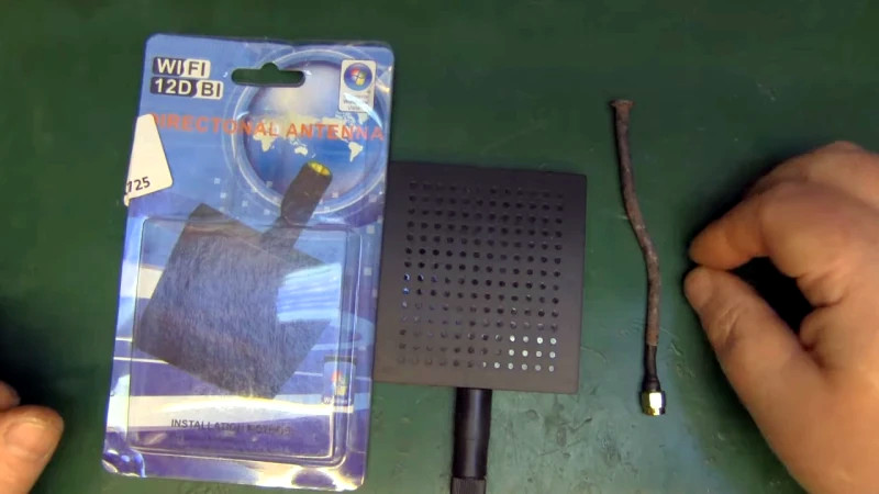
In general, you get what you pay for, and if what you pay for is a dollar-store WiFi antenna that claims to provide 12 dBi of signal gain, you shouldn’t be surprised when a rusty nail performs better than it.
The panel antenna that caught [Andrew McNeil]’s eye in a shop in Rome is a marvel of marketing genius. He says what caught his eye was the Windows Vista compatibility label, a ploy that really dates this gem. So too does the utterly irrelevant indication that it’s USB compatible when it’s designed to plug into an SMA jack on a WiFi adapter. [Andrew]’s teardown was uninspiring, revealing just a PCB with some apparently random traces to serve as the elements of a dipole. We found it amusing that the PCB silkscreen labels the thru-holes as H1 to H6, which is a great way to make an uncrowded board seem a bit more important.
The test results were no more impressive than the teardown. A network analyzer scan revealed that the antenna isn’t tuned for the 2.4-GHz WiFi band at all, and practical tests with the antenna connected to an adapter were unable to sniff out any local hotspots. And just to hammer home the point of how bad this antenna is, [Andrew] cobbled together a simple antenna from an SMA connector and a rusty nail, which handily outperformed the panel antenna.
We’ve seen plenty of [Andrew McNeil]’s WiFi antenna videos before, like his umbrella and tin can dish. We like the sanity he brings to the often wild claims of WiFi enthusiasts and detractors alike, especially when he showed that WiFi doesn’t kill houseplants. We can’t help but wonder what he thinks about the current 5G silliness.


I would be suspicious of your test setup with the sudden jump at 2.4 GHz. I would wonder if you have a calibration artifact.
You didn’t say, but what parameter are you looking at? Return Loss (Mag(S11)) – Does a open/shorted 6dB pad return -12 dB RL?
I’ve seen a fair number of these kinds of PCB antennas, and it won’t be omni. If nothing else, it’s going to have a distinct elevation pattern (assuming the feed is vertical). It’s two dipoles separated by (guessing from the scale) about 5 cm (which is a bit shy of half a wavelength). The relative phasing is hard to figure out, since we don’t have dimensions of the microstripline or the epsilon of the substrate.
However, given that the substrate isn’t free space, the total dipole length of 5cm may, in fact, be longer than a half wavelength, and a 3/2 wavelength dipole, for instance, has 3dbi gain (compared to 2.5 dBi). If the epsilon of the substrate were, say, 4, then that 5cm long dipole is actually close to a wavelength, and might have a gain of 4-5 dBi. yeah, the feedpoint impedance is high, but there are a bunch of stubs and patches on the PWB, so they could be doing a some matching without too much trouble – a combination of transmission lines and lumped values.
So we have, potentially, a 4-5 dBi radiator about 1/2 wavelength away from another 4-5 dBi radiator. If they’re in phase, then broadside to the array, you could pick up another 3dB. There is also that stub sticking up parallel to the two dipoles that looks sort of like a shorted transmission line. That might just be a matching component, and it probably doesn’t radiate much.
If, on the other hand, the dipoles are phased so that they are endfire array, the gain could be a bit different. As I noted earlier, they look like they’re a bit less than half a wavelength apart. It’s well known that you can have very high gains for two closely spaced dipoles (the W8JK is an example) (with 0.1 lambda spacing, you get 8-9 dB gain over the element gain), but here, probably about 3 dB, maybe a bit more.
In summary, without making any measurements, by physical inspection, I’d expect this thing to have around 8-9 dBi gain – yes, it’s not 12dBi, but it’s probably better than a rusty nail.
If you want to evaluate the gain claims, why not set up a little antenna range with a known source at a distance, some absorber, or do it outside so reflections aren’t a problem. You could have a reference dipole to compare, and then you’d look at the RSSI (may or may not be accurate) or use a step attenuator to match levels into the same receiver.
Ultimately, though, I’m really suspicious of that sudden jump of >20dB at 2.4 GHz. something weird is going on in your measurement setup.
This smells kinda right without getting into it too much. To get gain you have to compress the lobe so to speak, which means it gets more directional.
I might go so far as to say, that it’s unpossible to make a bad antenna that does worse than a rusty nail. It’s like trying to patch a firehose with masking tape, in the process of not working it’ll leak out/in signal everywhere and act like a simple stub. It takes as much good RF design to null the signals you don’t want as to get more gain on the signals you do.
Well, if as stated, the antenna is actually working as a bandstop filter at the wi-fi frequency range, then its possible to perform worse than a rusty nail by the fact that you’re filtering the signal out.
Could be that some fly-by-night Chinese company got a hold of a shipment of 2.4 GHz bandstop filters and went, “Hmm… who would buy these?”. Not much different from counterfeiters hot-gluing cut-off USB cable heads inside plastic covers and selling them on as thumb drives.
On the third hand (one foot?), blocking wi-fi signals might actually help your wireless work better. All of those 30 random SSIDs you get when you scan just add up noise to your network and if you have a really powerful antenna, the input to your wi-fi adapter may saturate and mess up the reception. The usual response then is to turn up the transmitting power of your router, which then further messes it up, and then installing a 2.4GHz blocking “antenna” on your adapter sitting 15 ft away magically cures it.
Sometimes you really have to wonder if the savings is really enough to warrant a fake.
I picked up some “USB 3.0″ micro-usb cables (just short ones, like 8” or so) and they looked good from the outside. Had the blue plastic inside the A end and the wider 9-pin metal shield on the micro-B end. Got them from China for around the usual ebay price of $0.99 or such. They weren’t coming up as USB 3.0, however, when plugged into my phone and the computer. So I figured they were flakey cords. But then the plastic boot around the micro-B end broke and I saw that it had only 4 wires going through it, instead of 9. Broke open the A end and, sure’nuf, there was only 4 contacts.
Seriously, was the penny or so it saved them worth the badwill and the refund costs?
It’s not about savings – its a bunch of people that get a pile of off-market stuff on their lap, for all we know they may have even stolen a shipping container full of the stuff and another with a bunch of plastic cases and think “Hmm…”.
>sure’nuf, there was only 4 contacts
Most likely reason: manufacturing defect. The factory accidentally used the wrong cable and the workers did what they were told. The result is a batch of faulty cables that would go to landfill and loss – so they sell them anyways through other channels.
When the product is free, and many of the customers won’t notice the difference or don’t bother to claim refund for a dollar item, you’re making profit regardless. And the “refund cost” is essentially a short term low-interest loan to the company just like cash-backs are: the company gets the money for a month and can invest with it before they have to return it.
There is definitely an issue with his test setup, the video of the working antenna shows the same huge offset at 2.4GHz despite the antenna otherwise being a well behaved antenna. If I had to hazard a guess, I would say that the leveling on his 8350 sweep generator is not working correctly, and when it switches out of the lowband (.01-2.4GHz on most plugins) there is a jump in the power. The weird thing is that he has the reference channel connected in that video, which should have accounted for any power shifts from the source even without doing any calibration, but maybe he just didn’t take the time to set the instrument up correctly.
That said – I am pretty sure the antenna is actually a 5GHz one. The packaging is set up for both bands, and while the 2.4GHz box is checked it is pretty likely that the wrong antenna design was put in the box. It would also explain why the board is smaller than the housing, since the housing was designed to also fit the larger 2.4GHz design.
you nailed it loll impressive work
He rusty nailed it.
I’ll drink to that. ;-)
I thought the worst wifi antenna was the $20 “FonTenna” from the nearly-defunct company that was giving away free wifi routers back in 2007, in exchange for selling your wifi to strangers and keeping well over half of the revenue. The FonTenna DID NOT boost range to 1.5 miles.
http://elfonblog.fondoo.net/2007/06/05/fontenna-is-now-shipping/
http://elfonblog.fondoo.net/2007/07/06/la-naked-fontenna/
http://elfonblog.fondoo.net/2007/06/29/la-fontenna-review/
Other considerations aside, rust is transparent to RF so it really doesn’t matter whether it was a rusty or clean nail.
How would skin effect come into play?
As far as I understand, if the rust is not conductive, it doesn’t matter much in skin effect…
Darn, i was hoping the rust was acting as some kind of weird fractal radiator.
I think surface roughness would have to get to 1/8 of a wavelength before you noticed much effect.
Maybe not – a rough surface makes the “conductive path” longer, so more AC resistance. Skin depth is probably less than a micron, so the RF is being carried in a *very* thin layer on the surface of the steel, so ripples and wiggles make the path longer. Of course, energy also couples via the magnetic field from the surface of the downslope across the valley to the upslope on the other side.
I’ll bet someone, somewhere did a detailed analytical consideration of this for their Master’s thesis in the 1940s -1960s. Who knows, Rayleigh or a contemporary may have published something on it in the 19th century: “On the AC resistance of rough conductors at high frequencies”, or, as it would show up in something like Annalen der Physik, “Über den Wechselstromwiderstand rauer Leiter bei hohen Frequenzen”
The iron in the nail underneath the rust is magnetic, so it has a very severe skin effect and shouldn’t really conduct at all for RF. The skin depth at 1 GHz is 64 nanometers.
> it’s designed to plug into an SMA jack on a WiFi adapter.
That would be something! Perhaps it was really just reverse SMA though. Are folks leaving out the “reverse” these days? That’s ok: up is down, true is false, left is right.
I think a via (or better a couple of them) are missing. The coax shield seems not electrically connected to anything, and i think it should be connected through vias to the bottom layer to complete the other dipoles half elements.
under the blob of silicone. I’ve fooled with a lot of these inexpensive antennas, and typically they just solder the shield and center conductor to pads with or without a through hole, and cover it with a blob of silicone as a strain relief.
There are other obvious plated through vias on the board (the end of that weird stub, for instance)
Jim, I have a question for you regarding a project. What is the best way to contact you?
Well, detailing everything that’s wrong with this “analysis” would take far more time than I have. You first need to measure return loss. That will tell you the antenna impedance and SWR. Does that give much of a clue about performance? No. Your nail is ferrous. That crowds current into a thinner layer than you get with a decent non-ferrous conductor. Loss will be very high. Even if the SWR appears useful, most of that is due to loss rather than radiation. You think it’s a 1/4L monopole. That requires a ground plane. You have none. The cable is acting as a counterpoise. Some ferrite in the right place will change everything as will cable length and placement. Performance of this antenna is undefined. You need a test antenna with defined performance to compare actual path loss of two antennas to assess loss versus actual radiation. Your comparison of a nail versus the panel antenna has so many holes that it’s entirely invalid.
You have not measured the azimuth pattern. You’re assuming that the panel is a broadside antenna. The two dipole elements on the PCB are slightly different lengths. Physical length does not equate to electrical length here. The board has a substantial dielectric constant. There are obvious matching elements. It may look simple but it is not. To me, this looks more like a 3-element Yagi which would make it end-fed. Maximum gain along the axis of the panel, not perpendicular to the panel. There will be a significant front/back ratio. You didn’t rotate the antenna so you have no clue. Any gain above 0 dBi presupposes a directional pattern, either in azimuth or elevation or both. The close proximity of your antenna to the test equipment will have a huge effect on the pattern. Needs to be more of a free field condition. Having a bench full of RF equipment doesn’t necessarily imply expertise. The panel antenna could indeed be 12 dBi if measured properly.
I think more a 2 element dipole array – depending on dimensions, could be either broadside or end fire (W8JK style). Yes, since the two dipoles are of slightly different length, and/or the matching networks could put some phase shift, it could be endfire, with a slight bias towards one end or the other.
Contrary to the video’s assertions, I think this is anything but a casual design. I’m sure it started as a decent model in a tool, and then there’s some cut and try to improve it, and to (most important) reduce the production cost. The model would be the bare PWA, and then they’d put it in the housing, and tweak it (a bit).
I’ve seen similar low cost antennas where it’s an air dielectric patch made of brass folded carefully, over a ground plane with some interesting little wiggles and tabs on the feed network. It was *obvious* that “design for low cost” was important – it all snapped together with the plastic housing to hold stuff in place, and that the things with high tooling cost (the injection molded housing) was used for more than one antenna model. And the thing works – works well.
That said, 12dBi might a bit of a stretch. There is, after all, the Chu-Harrington constraint on size, Q, and efficiency.
Though I would say we’re not in a realm of operation where skin depth really matters, not enough power involved. It’s like your old widower being perfectly happy with his 1/2″ plumbing, but when a family buys his house they can’t fill a sink when the laundry is on, anyone in the shower is always getting frozen or scalded, more current required, greater c.s. area of pipe. So unless you’re making antennas out of really fine gauge florist wire or twist ties, I don’t think these power/signal levels will choke it. ( Personal experience: experimented with 4 bay bowtie TV antennas using “coathanger” wire, sourced some nice 12G copper at last… not one freaking decimal of difference.) However, you’ve also got a resistance proportional to length issue, so with longer wavelengths and dipoles it will probably be more noticeable. Telescopic antennas are often ferrous.
Losses from skin effect aren’t power dependent. Melting at high powers from increased AC resistance would be. We’re clearly not in that regime.
So the clogged pipes analogy (flow rate limiting from reduced cross section with fixed head pressure) isn’t quite right. A X% loss is an X% loss.
We had some experience at work with using titanium for antennas (high shock environment) at 400 MHz. Short answer – it makes a huge difference compared to aluminum (resistivity of 55 vs 2.65). Steel isn’t quite as bad (about 10:1 resistivity compared to copper- and the thinner skin layer because of magnetic material). But if the ac resistance is an ohm with steel and 0.01 ohm for copper, compared to 50-70 ohms radiation resistance (the coathanger 1/2 dipole or the telescoping whip), then it’s negligible.
Yes, prior to melting though you get increased resistance with heating though, which we would not expect to see, the heating being so minor that it’s easily absorbed by environment, such that temperature can be assumed constant, until we get significantly more power.
From the moment I saw the pic of the rusty nail with the rp-sma connector I started picturing an eBay listing.
Just imagine it, caption – “Wifi Antenna”, a picture and in the description “Oh come on, give it a try. It won’t be the sketchiest WiFi device you have ever bought here.”
Made in China quality and seller ethics. I wish they evolved much crappier viruses instead.
I am a bit disappointed that he never plugged the rusty nail into the network analyzer. It would be great to find out that he stumbled upon a resonant antenna without even trying.
On a more serious note, how safe is it to plug random antennas into typical WiFi devices or even to change out the antenna without turning it off? Can reflected power do damage? Or is the power so low that even if it’s all reflected there isn’t enough to hurt anything? Or do they have really good protection circuits for that?
It’ll really just yoyo up and down between the impedance mismatch and the output stage dissipating as heat in the transmission line, which may be part coax, part PCB. Worry about it when you’re trying to crank out a few hundred watts and your feedline starts smoking :-D
Most of the inexpensive WiFi chips are pretty load insensitive. it’s 100mW (max) RF. The worst that happens with a mismatch is that either the current output is higher (shorted) or voltage is higher (open circuit). In both cases, no damage occurs. A lot of these chips have test numbers for a 50 ohm system, because that’s what your test equipment is, but in practice aren’t in a matched system. After all, there’s typically not much transmission line loss to worry about. It’s kind of like a DC power supply – you don’t worry that your load is “matched” to the power supply. 100mW is a bit more than 2V rms, so you’re not worried about a 100% reflection exceeding the max voltage rating on the output transistor.
A designer might focus more on the “whole system” and optimize the antenna to have the radiated power constant across the band, within the regulatory limits at the high end, and to keep spurious signals down. They’re typically NOT concerned (in a thing that plugs into the wall and draws Watts already) with eking out the last few percent of DC-RF conversion efficiency for a 100 mW transmitter.
90% of made in China products these days lie about all their specs so you have to have the common sense to know that their claims are impossible.
Using Dbi as a reference is the first warning sign since it is impossible to build a “isotropic” antenna to prove them wrong.
REAL antenna companies use gain over a DIPOLE or over a 1/4 wave as a reference since it is the ONLY provable and repeatable reference.
You get what you pay for in this world and NONE of those cheap Chinese gimmicks EVER deliver on their claims.
The TV antenna market is full of lies and fake gain specs these days as well.
A quick search of Amazon or Ebay will find dozens of indoor antennas claiming a 990 mile range or more.
Yet in reality a paper clip will out distance them.
They lie because it sells product.
There are millions of gullible people online that fall for these scams thousands of times every day and will never learn
If you buy MADE IN USA, you get the BEST quality and FTC regulated advertising but even THEN you need to use common sense.
When a tv huckster shows himself in a boat using a $1 set of rabbit ears to watch tv, you need to understand that he buys those antennas from Chinese SLAVEs for under a dollar and sells them to YOU for $19.95.