The Crystal (High Voltage) Method

Do high voltages affect the resonant frequency of a crystal? Honestly, we never thought about it, but [Joe] did and decided to risk his analyzer to find out. He started with some decidedly old-school crystals like you might have found in a 1960-era Novice rig. Since the crystal is piezoelectric, he wondered if using a high DC voltage to bend the crystal to move the frequency to create a variable crystal oscillator (sometimes called a VXO).

He created a rig to block DC away from the network analyzer and then feed voltage directly across the crystal. The voltage was from an ESD tester that provides over 1000 volts.

Getting a crystal to change much in frequency is difficult, which is why they are useful. So we weren’t surprised that even at very high voltages, the effect wasn’t very large. It did change the frequency, but it just wasn’t very much.

At one point, it looked like he might have killed the test equipment. There was a time when letting the smoke out of a network analyzer would have been a costly mistake, but these days the cost isn’t that prohibitive. In the end, this experiment probably doesn’t produce any practical results. Still, it is interesting, and we always enjoy watching anything that gives us more intuition about the behavior of circuits or, in this case, circuit elements.

If you need a refresher on crystal oscillators, we can help. There are other ways to modify a crystal’s frequency, of course.

Continue reading “The Crystal (High Voltage) Method”

The Rusty Nail Award For Worst WiFi Antenna

In general, you get what you pay for, and if what you pay for is a dollar-store WiFi antenna that claims to provide 12 dBi of signal gain, you shouldn’t be surprised when a rusty nail performs better than it.

The panel antenna that caught [Andrew McNeil]’s eye in a shop in Rome is a marvel of marketing genius. He says what caught his eye was the Windows Vista compatibility label, a ploy that really dates this gem. So too does the utterly irrelevant indication that it’s USB compatible when it’s designed to plug into an SMA jack on a WiFi adapter. [Andrew]’s teardown was uninspiring, revealing just a PCB with some apparently random traces to serve as the elements of a dipole. We found it amusing that the PCB silkscreen labels the thru-holes as H1 to H6, which is a great way to make an uncrowded board seem a bit more important.

The test results were no more impressive than the teardown. A network analyzer scan revealed that the antenna isn’t tuned for the 2.4-GHz WiFi band at all, and practical tests with the antenna connected to an adapter were unable to sniff out any local hotspots. And just to hammer home the point of how bad this antenna is, [Andrew] cobbled together a simple antenna from an SMA connector and a rusty nail, which handily outperformed the panel antenna.

We’ve seen plenty of [Andrew McNeil]’s WiFi antenna videos before, like his umbrella and tin can dish. We like the sanity he brings to the often wild claims of WiFi enthusiasts and detractors alike, especially when he showed that WiFi doesn’t kill houseplants. We can’t help but wonder what he thinks about the current 5G silliness.

Continue reading “The Rusty Nail Award For Worst WiFi Antenna”

DIY Scalar Network Analyzer

[Steven Merrifield] built his own Scalar Network Analyzer and it’s a beauty! [Steve]’s SNA has a digital pinout matching a Raspberry Pi, but any GPIO could be used to operate the device and retrieve the data from the ADC. The design is based around a few tried and true chips from Analog Devices. He’s taken some care to design it to be nice and accurate which is why he’s limited it to 1kHz to 30Mhz. We think it’s quite a fetching board once the shielding is in place.

We’ve covered network analyzers and their usefulness before. If you want to know how, for example, a mystery capacitor from your junk bin will respond to certain frequencies, a network analyzer could tell you. We’ve even taken a stab at hacking together our own.

There is more documentation on his website as well as some additional example curves. The board is easily ordered from OSHpark and the source code is available for review.

Analog Discovery 2 As A Vector Network Analyzer

A while back, I posted a review of the Analog Discovery 2, which is one of those USB “do everything” instruments. You might recall I generally liked it, although I wasn’t crazy about the price and the fact that the BNC connectors were an extra item. However, in that same post, I mentioned I’d look at the device’s capabilities as a network analyzer (NA) sometime in the future. The future, as they say, is now.

What’s an NA?

In its simplest form, there’s not much to an NA. You sweep a frequency generator across some range of frequencies. You feed that into some component or network of components and then you measure the power you get out compared to the power you put in. Fancy instruments can do some other measurements, but that’s really the heart of it.

The output is usually in two parts. You see a scope-like graph that has the frequency as the X-axis and some sort of magnitude as the Y-axis. Often the magnitude will be the ratio of the output power to the input power as a decibel. In addition, another scope-like output will show the phase shift through the network (Y-axis) vs frequency (X-axis). The Discovery 2 has these outputs and you can add custom displays, too.

Why do you care? An NA can help you understand tuned circuits, antennas, or anything else that has a frequency response, even an active filter or the feedback network of an oscillator. Could you do the same measurements manually? Of course you could. But taking hundreds of measurements per octave would be tedious and error-prone.

Continue reading “Analog Discovery 2 As A Vector Network Analyzer”

Network Analysers: The Electrical Kind

Instrumentation has progressed by leaps and bounds in the last few years, however, the fundamental analysis techniques that are the foundation of modern-day equipment remain the same. A network analyzer is an instrument that allows us to characterize RF networks such as filters, mixers, antennas and even new materials for microwave electronics such as ceramic capacitors and resonators in the gigahertz range. In this write-up, I discuss network analyzers in brief and how the DIY movement has helped bring down the cost of such devices. I will also share some existing projects that may help you build your own along with some use cases where a network analyzer may be employed. Let’s dive right in.

Network Analysis Fundamentals

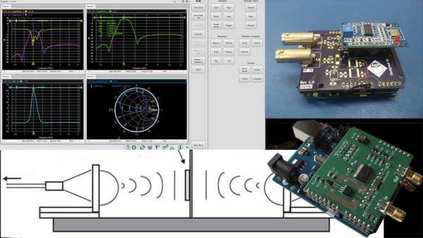
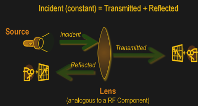
As a conceptual model, think of light hitting a lens and most of it going through but part of it getting reflected back.

The same applies to an electrical/RF network where the RF energy that is launched into the device may be attenuated a bit, transmitted to an extent and some of it reflected back. This analysis gives us an attenuation coefficient and a reflection coefficient which explains the behavior of the device under test (DUT).

Of course, this may not be enough and we may also require information about the phase relationship between the signals. Such instruments are termed Vector Network Analysers and are helpful in measuring the scattering parameters or S-Parameters of a DUT.

The scattering matrix links the incident waves a1, a2 to the outgoing waves b1, b2 according to the following linear equation:
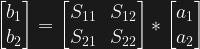
 \begin{bmatrix} b_1 \\ b_2 \end{bmatrix} = \begin{bmatrix} S_{11} & S_{12} \\ S_{21} & S_{22} \end{bmatrix} * \begin{bmatrix} a_1 \\ a_2 \end{bmatrix} .

The equation shows that the S-parameters are expressed as the matrix S, where and denote the output and input port numbers of the DUT.

This completely characterizes a network for attenuation, reflection as well as insertion loss. S-Parameters are explained more in details in Electromagnetic Field Theory and Transmission Line Theory but suffice to say that these measurements will be used to deduce the properties of the DUT and generate a mathematical model for the same.

General Architecture

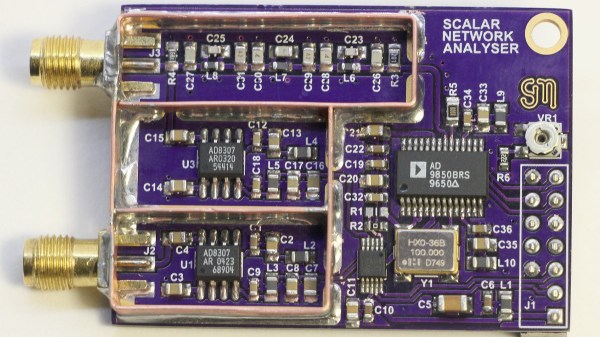
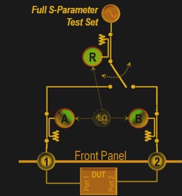
As mentioned previously, a simple network analyzer would be a signal generator connected and a spectrum analyzer combined to work together. The signal generator would be configured to output a signal of a known frequency and the spectrum analyzer would be used to detect the signal at the other end. Then the frequency would be changed to another and the process repeats such that the system sweeps a range of frequencies and the output can be tabulated or plotted on a graph. In order to get reflected power, a microwave component such as a magic-T or directional couplers, however, all of this is usually inbuilt into modern-day VNAs.
Continue reading “Network Analysers: The Electrical Kind”

Handheld Network Analyzer Peek Inside

[Shahriar] recently posted a review of a 6.8 GHz network analyzer. You can see the full video — over fifty minutes worth — below the break. The device can act as a network analyzer, a spectrum analyzer, a field strength meter, and a signal generator. It can tune in 1 Hz steps down to 9 kHz. Before you rush out to buy one, however, be warned. The cost is just under $2,000.

That sounds like a lot, but test gear in this frequency range isn’t cheap. If you really need it, you’d probably have to pay at least as much for something equivalent.

[Shahriar] had a few issues to report, but overall he seemed to like the device. For example, setting the step size too broad can cause the spectrum analyzer to miss narrow signals.

If your needs are more modest, we’ve covered a much simpler (and less expensive) unit that goes to 6 GHz. If you need even less, an Arduino can do the job with a good bit of help. The Analog Discovery 2 also has a network analyzer feature, along with other tools at a more affordable cost, too. Of course, that’s only good to 10 MHz.

Continue reading “Handheld Network Analyzer Peek Inside”

Review: Digilent Analog Discovery 2

I recently opened the mailbox to find a little device about the size of White Castle burger. It was an “Analog Discovery 2” from Digilent. It is hard to categorize exactly what it is. On the face of it, it is a USB scope and logic analyzer. But it is also a waveform generator, a DC power supply, a pattern generator, and a network analyzer.

I’ve looked at devices like this before. Some are better than others, but usually all the pieces don’t work well at the same time. That is, you can use the scope or you can use the signal generator. The ones based on microcontrollers often get worse as you add channels even. The Analog Discovery 2 is built around an FPGA which, if done right, should get around many of the problems associated with other small instrumentation devices.

I’d read good things about the Discovery 2, so I was anxious to put it through its paces. I will say it is an impressive piece of gear. There are a few things that I was less happy with, though, and I’ll try to give you a fair read on what I found both good and bad.

Continue reading “Review: Digilent Analog Discovery 2”