They say that drummers make the best helicopter pilots, because to master the controls of rotary-wing aircraft, you really need to be able to do something different with each limb and still have all the motions coordinate with each other. The control complexity is due to the mechanical complexity of the swashplate, which translates control inputs into both collective and cyclical changes in the angle of attack of the rotor blades.
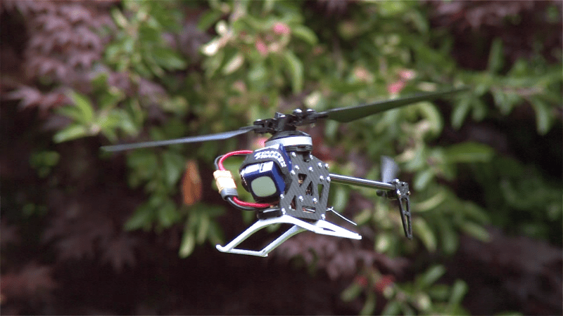
As [Tom Stanton] points out in his latest video, a swashplate isn’t always needed. Multicopters dispense with the need for one by differentially controlling four or more motors to provide roll, pitch, and yaw control. But thanks to a doctoral thesis he found, it’s also possible to control a traditional single-rotor helicopter by substituting flexible rotor hinges and precise motor speed control for the swashplate.
 You only need to watch the slow-motion videos to see what’s happening: as the motor speed is varied within a single revolution, the tips of the hinged rotor blades lead and lag the main shaft in controlled sections of the cycle. The hinge is angled, which means the angle of attack of each rotor blade changes during each rotation — exactly what the swashplate normally accomplishes. As you can imagine, modulating the speed of a motor within a single revolution when it’s spinning at 3,000 RPM is no mean feat, and [Tom] goes into some detail on that in a follow-up video on his second channel.
It may not replace quadcopters anytime soon, but we really enjoyed the lesson in rotor-wing flight. [Tom] always does a great job of explaining things, whether it’s the Coandă effect or anti-lock brakes for a bike.


at a certain point: Physics dark magic
He has a video on his 2nd channel describing how he made it.
https://www.youtube.com/watch?v=Y31BhQToh_U
Very impressive, I fly the big ones so I understand how hard it is to do something like this. I’ve worked in R & D for Textron so I understand the fun your also having. Keep inventing!
Right? It boggles my mind that:
1) You can get that kind of precision from the motor control at 3k RPM
2) The hinge responds as needed at that speed
This has to put an enormous amount of wear and strain on that hinge, right?
Well, classic helicopter rotor are also doing a similar movement aren’t they? So I would say that wear and tear would be similar if not less due to the fact of being at 45 degrees (Instinctivly there is more contact area ?)
Also I would be very interested in how a compliant mechanism would behave! Like just print the whole rotor at once, no hinge (or maybe to fix the blade). Starflex rotors are compliant system with the traditional helicopter pitch control.
Neat trick. So the two axes of cyclic is controlled by the phase and amplitude of the modulation of the rotor speed. For collective, you’re stuck with just controlling the speed, but that’s not so bad — pretty much every electric rotorcraft does that anyway.
I wonder if it can do autorotation? Power would obviously be required to do the modulation so it a moot point anyway, but is it even physically possible with that kind of no-collective rotorhead?
I would think it can autorotate all the way into the ground…. lacking the method to flare it at the last second by converting all the angular momentum to lift.
You’d lose all control over where you’d … “land”… as well. If you were going forward before losing power you’d be going forward after, and losing altitude at a very great rate.
I don’t think autorotation is possible with fixed-pitch helicopters. You need collective pitch to control rotor RPM during the descent.
Quite impressive, although it seems like this would be limited to electric-powered helicopters. That sort of control is difficult enough with a brushless electric motor, but I can’t imagine how you’d pull it off with a gas turbine!
Borrow ideas from diesel trains.
Diesel trains have almost no weight constraints
being really heavy is actually beneficial for the locomotive :D
I really don’t understand this as it applies to a 2 bladed application. The only way I can imagine it having cyclic is if the leading blade has positive and the opposite blade has a negative pitch differential with additional speed/drag/delay. Is this how it works?
The rotors appear to be set such that one goes positive under acceleration and the other negative. This is inverted for deceleration. presumably this has to track which rotor is forwards such that it can match the acceleration and deceleration overlaid on top of the otherwise constant rotation.
most likely this is imposing some sort of sinusoid with a period matching the current rotational period.
As stated in the video this is exactly what happens. Also a magnetic plate is attached to the motor so absolute position can be read with an external hall effect sensor.
This technique was originally pioneered by my colleague and friend Jimmy Paulos – fantastic guy and a great roboticist. Check out his papers on the topic.
He references Jimmy’s work rightaway in the video.
Love the sound of the modulated motor, makes it even more insect-like!
I never forgot about this paper and am really glad someone breathed some more life into the idea. However the more I thought about it, the more problems I saw with the idea. The ultimate being that that motor’s having to do a hell of a lot of work to accelerate and then decelerate your rotors once per revolution and your aircraft is only ever going to be as efficient as your regenerative braking system can be.
Keyence Revolutor did exactly this like 20 years ago. It had a main rotor shaft coupled with an optical encoder driven by a brushed DC motor and a pair of gyros(actual spinning gyros! Entire thing predates MEMS gyros)
Not sure if they had any academic papers for it but the one side of its two blade rotor was designed to flex in response to inputs exactly like this one does.
Found a video of one restored to flying condition https://youtu.be/8A3HydXXL8M They say the launch date was 1991 so almost 30 years ago.
this solution with the curved compliant blades is probably even more elegant, as it no moving hinge
I love Tom! His videos are a “drop everything and watch” event for me! I’ve been wondering when camera ‘drones’ are going to move back to a single main rotor. Much more efficient vs the more common quadcopter arrangement, but usually came with mechanical complexity. Will this be the change needed to do that? FPV racing and freestyle will probably always stick with quads due to their power and control, but if you are looking to stay in the air for as long as possible, less rotors the better.
Tom is the best. He documents some pretty crazy concepts, success or failure. Sometimes the failures are even more entertaining than the successes!
Instead of a hinged articulated blade, maybe put a couple of counter weights which change blade pitch with rotational torque.
Those are a bit complex, because when they can pull the pitch flatter at speed, but also if you try to overaccelerate them past the torsional rigidity of the blade they’ll pull backward, tending to force pitch coarser, but also having the risk of folding the blade. Probably also cause flutter oscillating between those two if you’re trying to accelerate the blade modestly. Also b0rks sensitive control because you want as little flywheel effect as possible to effect quick changes, not more mass in the system.
Oh but I may have misunderstood, were you suggesting a centrifugal regulator linkage closer to the mast?
Yes. Right at the blade root.
Or a spring and use the modulated inertia of the blade vs mast to change differential pitch.
I find this whole thing very innovative and fascinating. Modulating torque levels at partial rotation arcs at blade speed is very, very cool
I’m imagining really tiny choppers with very sophisticated software (which is easy to do now) and minimalist hardware.
Also imagining what kind of crazy control you might get from having 360 degree instant (and independent) cyclic on each blade of a quadcopter.
I Fly Helicopters for a living. This is very impressive for sure..
HaD featured a similar thing a while back, with a fixed pitch contra-rotating rotor coaxial to the hinged rotor for counter-torque.
Still wanting someone to use this concept to build a real flying version of the triangular (with a ducted prop in the center) camera drone in the “Runaway” movie with Tom Selleck, Kirstie Alley, Gene Simmons, and Cynthia Rhodes.
surprised this wasn’t considered for the new mars chopper, opting for a coaxial double swash design instead. seems you would want to reduce the complexity to the bare minimum necessary and to reduce weight.
“It may not replace quadcopters anytime soon,”
Never understood the draw of large quadcopters over helicopters myself. Except for maybe the aesthetics, helicopters are better in nearly every regard.
Yes, and I came across this article when looking for that one :-)
Well done, that man.