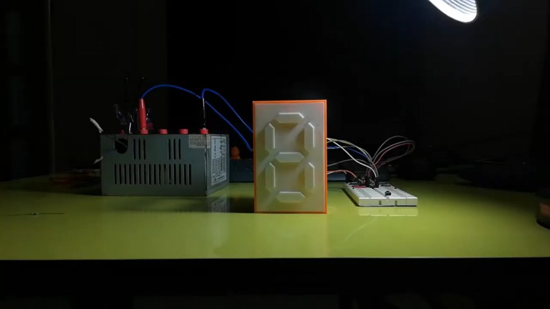
We’ve been displaying numbers using segmented displays for almost 120 years now, an invention that predates the LEDs that usually power the ubiquitous devices by a half-dozen decades or so. But LEDs are far from the only way to run a seven-segment display — check out this mechanical seven-segment display for proof of that.
We’ve been seeing a lot of mechanical seven-segment displays lately, and when we first spotted [indoorgeek]’s build, we thought it would be a variation on the common “flip-dot” mechanism. But this one is different; to form each numeral, the necessary segments protrude from the face of the display slightly. Everything is 3D-printed from white filament, yielding a clean look when the retracted but casting a sharp shadow when extended. Each segment carries a small magnet on the back which snuggles up against the steel core of a custom-wound electromagnet, which repels the magnet when energized and extends the segment. We thought for sure it would be loud, but the video below shows that it’s really quiet.
While we like the subtle contrast of the display, it might not be enough for some users, especially where side-lighting is impractical. In that case, they might want to look at this earlier similar display and try contrasting colors on the sides of each segment.


Very nice but it would be even cooler if it flipped to a different color and protruded.
Make the top layer out of opaque plastic and have a backlight – so when its in the forward position light leaks round the edges?
Or make it translucent with an LED in each section so its functionally it can work the same as a normal segment display while having that nice texture pop party trick?
Or do you mean push against only one side of the segment so it partially flips to reveal a normal colour?
Personally I like the top option more, be more unique in look and makes the mechanical function essential.
I think the same. This display already is really neat, though. 😎
Just love old school technology, such as relays, magnets, TTL chips and electron tubes.
Also “thumbs up” for that modified computer psu! :)
Here’s one that flips: https://youtu.be/pBoHq3AG8rw
I really love this execution, but because it’s still 3d printed, the segments arent totally flush to the face when retracted, and the printed finish contrasts with the surface finish of the front panel.
Kinda takes away from the effect. But it proves the concept well.
Next step- make the material face more seamless, and use a piece of brushed metal or even stone using a cnc- and then edge light the sections that pop out using EL wire recessed, or just LEDs.
If well executed and seamless, so its truly invisible when retracted, this would be absolutely stunning.
Ooh I actually kind of liked the subtle texture of the seams when its in, a little more finishing effort would help a little (fill, sand and fill, sand and sand… Oh god why chase great surface finishes….)
But if you could manage that sort of precision, that would be really quite awsome (and making it in right type of stone the patterns in the stone would hide the cracks really well – don’t think you will get a particularly seamless look with brushed metal though, at least not without needing real precision ground – Polished might look better at more attainable precision – while there will be cracks when something is really reflective it can be quite hard to spot them.).
I don’t think you realize the kind of precision I can execute this design in. Much higher than what he has done here with a 3d printer.
Precision ground is doable if metal, or stone. The gap for the segment cutouts can be very fine indeed, still huge to me, but if in a material like stone where you want to keep all the material in the same sheet in place for looks- 0.005″ gap should be doable with a certain technology beyond waterjet I can get access to if I talk with someone.. Waterjet would have a pierced spot for each numeral that would be maybe 0.020″ big, and maybe 0.015″ for kerf from cutting.
If it was solid metal, wire EDM- but not necessary. I’d just cut pieces to fit, 0.001″ fit doable, if everything is put on guide rods to pop out so they don’t bind. I’d make sure everything fits, then lap or grind or brush whole surface flat for seamless finish.
Yeah I’m not saying its impossible – but there is precision you can easily and quickly attain as a hobbyist.
And a properly set up FDM printer is somewhere around that top end, a bad one still not that far down the list..
Which as you say if you have access to the fancier tools or enough patience with a hand lap isn’t impossible to better. But hand lapping the 6 faces around the seven segments and the IMO much harder internal matching surfaces in the back panel for that really tight fit would be horrible, and take a very long time – especially if you are doing it to parts you have had to oversize deliberately to make up for the slop in whatever tooling you are using to make the blanks.
Doing the whole face afterwards is easy – and just doing that would improve the look a fair bit as long as you can consistently make it retract only the exact right amount.
No…you are missing the entire method ;)
Say its metal- use a normal endmill to cut most of the shape out in the main body, then go in with a very small diameter cutter, say, 0.030″, to get the smallest radius you can in the corners. Or, alternatively, broach the sharp corners. But let’s just say s tiny radius in corners is OK.
Cut it all on same diameter settings, and measure.
Cut the moving pieces second- and just cut to measure- so they can be fitted.
Very simple. The actual back pieces that are on the 3d printed version- I’d use precision guide pins in machined pockets to guide everything without binding.
If stone- well, there’s a special abrasive tool I can’t divulge that will do 0.005 kerf cuts through any material there is, including solid diamond, that I can get access to to very carefully plunge cut the numerals out with 0.005″ gap a side, so the stone pieces can stay in orientation.
Maybe in the next 10 years or so it will become more common- but for now, I know the sole importer of this tool. Can’t divulge any more- but anything is possible.
I’m not so much a hobbiest- I’m a professional that makes things for a hobby. I have a bit more techniques than the average maker.
Your method is exactly what I was thinking – its just beyond my tools to get that (at least reliably). Which would force lapping the whole damn lot down from oversize. And internal lapping I really don’t like – circular features are not too bad.. but lots of flat precise angles just takes so much effort.
I’d say most of our machines are likely to chatter or be wornout enough that trying to cut that near to target is rather tricky. Double maybe a little more the tolerance you are talking about is more in the sane range I’d say. I’ve done tighter, but when your tools are not new professional grade but either very worn old ones or cheap imports actually cutting metal to higher precision than a decently tuned FDM is pretty tricky – as the FDM has no cutting forces, even the cheapest ones use pretty good mechanisms for the forces they take and with fine nozzle and good consistent filament can get very very close to spec (remember to size up for the very consistent cooling shrink factor of course).. And if your printer is not that tuned to printing the correct dimensions it will still be consistent to itself at least.
Perhaps it would be worth trying a taut elastic sheet, e.g. rubber baloon, at the right distance in front of the segments. When not in actuated the elastic face should be flat and only when pushed by the segments a figure should pop up.
*when not actuated
Add a vacuum pump to the mix, to pull the sheet tight.
Maybe even go the other way – have the segments retract when “on”.
Why not color the sides of the segment in a different color, so it adds a bit of contrast when the segments pop out? Could probably make it with a simple color swap of filament, just print the first 2-3 layers in white, then switch to a dark filament. Just painting the sides of the segments is probably not that great, as that could rub off over time.
That is a good idea. I think that would indeed look cooler
I have really tried, but somehow I just can’t get into the whole seven-segment nostalgia. I think I just got woken up by a gang of them too many times during school/when I worked in kitchens. Left me with a deep, burning hate as dull and red as those crappy 80s LEDs.
The mechanics are always really cool, though.
I like this a lot but when I looked at the thumbnail, I imagined a elastic, featureless skin which would be stretched to reveal the segments as they pushed their way out.
Not sure what is wrong with my brain because that would be creepy.
Creepy awesome.
love it, would be great if you could create a clock like this for in the dark. Wake up at night keep eyes closed lean over and feel the time.
As silly as I think binary clocks are, that might be a good use for one. Would be much more efficient than feeling all the segments for all the digits.