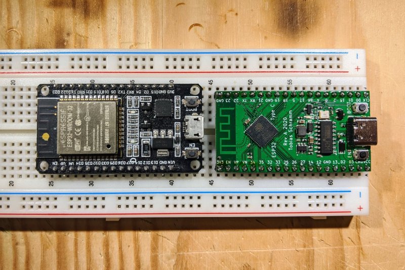
Sometimes the most useful hacks aren’t the flashiest, they’re the ones that improve an already great tool and make something better. Through hole components are still the fastest and perhaps most satisfying way to prototype a new electronics project so it’s extra frustrating when the happy hacker discovers their new devboard is too wide to fit in a standard breadboard. [Tobias] had the same thought and redesigned the standard ESP32 “NodeMCU” style devboard to be almost exactly the same, but narrower.
Not to trivialize, but that’s pretty much it. And we love it! The new design retains the great support of the original devboard but adds a few nice tweaks. Obviously there’s the small size change that allows it to fit on a standard 5×5 breadboard leaving sockets available on either side for interfacing. Even in this smaller size [Tobias] managed to retain the boot mode and reset buttons though the overall pinout has changed slightly. And for easier connections ye olde micro USB socket has been swapped for sleek modern USB-C. You have cables for that common standard now, right?
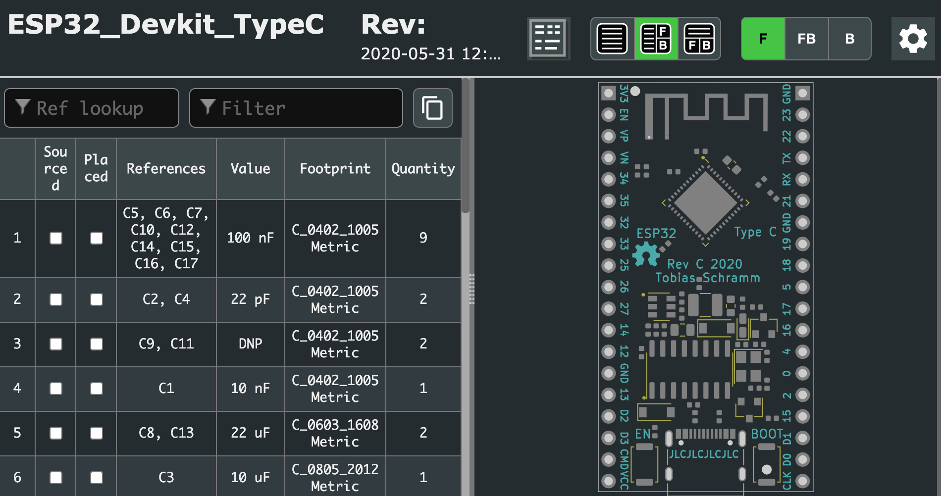
How do you get one? As far as we know [Tobias] isn’t selling these but the design is completely open source and the design, fab, and BOM files are all in the github repository. [Tobias] even went so far as to include the extremely handy interactive BOM to speed up hand assembly. The real trick here is that the board is designed to facilitate the extremely inexpensive turnkey assembly now available from our favorite fab houses, with an example cost of $8/piece for a run of five. The repo includes a properly formatted BOM and fab files to make ordering them a snap. See the bottom of the README for details about what to order.


What would this be?
—“ur favorite fab houses, with an example cost of $8/piece for a run of five.”
Probs JLCPCB. All the parts look like their in their P&P service library.
What I want to know is, why does nobody make breadboards with rows (or would it be columns?) wider than 5 pins? Or if they exist, where can I buy them?
excellent Question. Searched for them so many times, found none :(
Not buy, but to print it yourself (and use the metal parts of other breadboards) read this: https://www.instructables.com/id/Dev-Board-Breadboard/
You could just use 2 breadboards for each pin row to span the large gap.
Also allows one to still use the FCC stamped module.
However, I tend to avoid breadboards with generic perforated prototype board whenever possible. Nothing like corroded contacts or tape glue from though-hole leads ruining your day
;-)
I’m not sure this is a pro tip, but the good breadboards have removable power rails on the side, with little dovetaily things that they slide into. Instead, slide two boards together, and you have a deluxe mega-board.
/me has his own favorite breadboard, and isn’t ashamed to admit it.
True, but the 2×5 or 6 pins are not connected without jumpers between them…
I think the point is you straddle the larger component between two boards, then you still have 4 pins available on each board with the wide dev board taking up the 5th pin
That’s what I did years ago to adapt to these wide boards. This lot complaining about it still is pretty sad. I wish I knew their names so I don’t hire any of them accidentally.
The WEMOS32 is just for scale I know the pins wouldn’t work. I solder a row of pins on the outside on the bottom and a row of female headers on the inside rows on the top.
https://i.imgur.com/yAP3Urf.jpg
https://i.imgur.com/re3DDOG.jpg
Or, cut the breadboard that you have into two pieces and space then further apart: https://www.flickr.com/photos/anachrocomputer/albums/72157628745849693
I did the same with the cheap full-size Chinese breadboard in which the center space is too small due to plastic shrinkage (so not even any module fits)
Before that, I used those small 21×10 breadboard,one for each pin row.
I didn’t know this was even a problem – the few I have are 6 row. Bought in the UK years ago, probably in sales from the now-defunct Maplin. But made by K and H which still seem to be going. Their AD range seems to have 6 rows, others have 5.
Even for the slimmer version, you would likely need jumpers if you have more than 1 connection.
Might as well use a female jumper directly on the header pins as an extension cable. It would also save space on the breadboard.
The UK based website below stocks them:
https://www.rapidonline.com/k-h-ad-102-advanced-solderless-breadboard-456-tie-points-34-0676
Finaly!!! This was bugging me for years…
If you need more than 5 connections on one pin, the breadboard is trying to tell you that you need to stop using a breadboard for that project – your project has gotten too big and complicated.
Yes, 5 is somehow encoded into the pattern of the universe and don’t fuck with that.
The only slightly less well-known of Kirchoff’s laws is this: Never form a node where the fanout is more than 5.
heh. I remember reading something many years ago about the fanout from TTL to 5v CMOS being infinite and thinking that can’t be right. there’s got to be some current, right?
I noted this in the https://github.com/TobleMiner/ESP32-Devkit-Type-C post…
“DISCLAIMER: I’ve not tested this design yet”
It would be nice to have a note to say if it works or not.
2 months ago the posts were, so I wonder if the board design was ok?
I was wondering this as well. Sounds like the earlier revision of the design was good, and the current one probably is too.
https://twitter.com/Toble_Miner/status/1287644235525758976
There’s the “Widora Air” which is an ESP32 dev board only slightly larger than a 40 pin DIP chip.
ezsbc did this and has been selling these for a few years now, a great product —
https://www.ezsbc.com/index.php/products/wifi01-33.html#.XyQ-YhJ7mpo/
It’s a little inconvenient but you can always install two rows of headers to fit and mark the module width, then connect to the holes between them.
I had a similar problem with the ESP32 boards and the STM32 eval boards. My elegant solution was to remove the power bus from the Protoboards and then set two halves of the board Side by side. With the power bus on the far outside. Simple 5 minute solution. And I get 3 more pins on each side. Doesn’t everybody do this ?
I purchased 2 identical Breadboards and snapped them together side by side specifically for use with ESP 32/8266 boards.
This has additional benefit of reducing hookup wire clutter when connecting an LED & Resistor from an I/O pin to the power rail as you have 2 divided terminal strips on each side of the of the ESP.
so… no matching network to the antenna?
I’ve seen F antennas without any matching passives. Looks he tried to copy the antenna design over. Yeah, good luck with that.
This board uses the ESP32 Pico D4. The ESP32 Pico D4 has an internal matching network eliminating the need for an external one. The antenna used is the same Espressif uses and has an impedance of about 50 ohms. It has actually been designed by TI and is detailed in AN043.
ESP’s and other large size boards is one reason I make my Proto-boards with 6 holes per row. https://github.com/jscottb/pcbs
This is really nothing new. I picked up an ESP32 nodemcu like board months ago that will fit a breadboard leaving a row of pins open at each side, and said board still uses the complete ESP32 module, rather than the discreet chip. Look up the Wemos LOLIN32 boards.