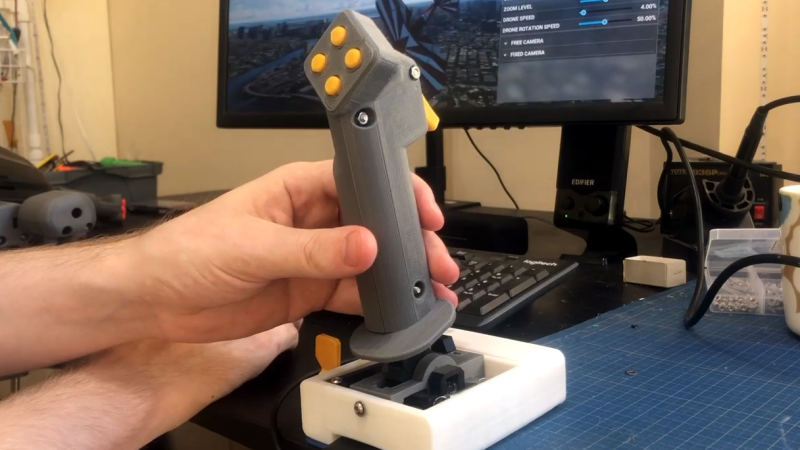
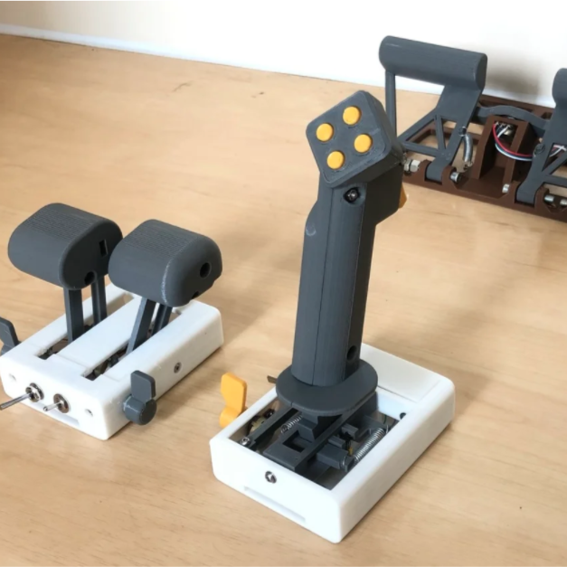
 We have seen quite a few DIY joystick designs that use Hall effect sensors, but [Akaki Kuumeri]’s controller designs (YouTube video, embedded below) really make the most of 3D printing to avoid the need for any other type of fabrication. He’s been busy using them to enhance his Microsoft Flight Simulator 2020 experience, and shares not just his joystick design, but makes it a three-pack with designs for throttle and pedals as well.
Hall effect sensors output a voltage that varies in proportion to the presence of a magnetic field, which is typically provided by a nearby magnet. By mounting sensors and magnets in a way that varies the distance between them depending on how a control is moved, position can be sensed and communicated to a host computer.
In [Akaki]’s case, that communication is done with an Arduino Pro Micro (with ATmega32U4) whose built-in USB support allows it to be configured and recognized as a USB input device. The rest is just tweaking the physical layouts and getting spring or elastic tension right. You can see it all work in the video below.
Hall effect sensors have featured in DIY joystick builds, but for something as delightful as it is different, don’t miss this fantastic high-speed magnetic imager based on them.


Anyone made a sim wheel using that hall effect technique?
If it’s a racing wheel you’d probably prefer a motor based solution so you can get the feedback.
On a flight system having feedback doesn’t seem to be a priority. Though it makes me wonder if fly by wire systems in real planes have feedback.
Airbus sidesticks use spring pressure for feedback. Increasing deflection requires increasing force. The roll rate commanded is proportional to the left/right deflection and the g load in pitch is commanded by the amount of forward/back deflection.
So the feedback in an Airbus sidestick is really feedback about what you’re telling the flight computers to make the aircraft do, not physical feedback from the flight surfaces themselves.
It seems a stretch to call this “force feedback”, it’s just a spring to center the stick. Almost all joysticks have had this since the early Atari days.
Interesting, so it’s truly just the same as a toy joystick.
I fly IRL gliders, in a small airplane like that you can definitely feel the resistance and feedback from the control surfaces through the flight stick. It can tell you a bit about if you’re close to a stall and how fast you’re going (but I’m sure you could still fly without those pieces of info, you can tell those two things well enough by other means).
Am I right to assume these non-feedback fly-by-wire control sticks on Airbus still have the rumble for stall warning?
Under normal conditions a modern Airbus will not stall – the flight control computers limit the angle of attack. With no back stick pressure the airplane can slow until the angle of attack reaches the ‘alpha protection’ range, at which point the flight computers will maintain that angle of attack. If the pilot maintains full back pressure, the flight control computers will let the angle of attack go up to ‘alpha max’ – the maximum angle of attack without stalling.
If the aircraft has lost redundancy in angle of attack sensors, pitot probes, or had other specific failures, the ‘normal law’ flight laws downgrade to ‘alternate law’ and then ‘direct law’. Since the computers lack full information, they give control back to the pilot. In those modes the airplane can be stalled. In that case the flight warning system will verbally announce ‘Stall, Stall.’
Do any current games support motor force feedback? I loved my side winder but got rid of it awhile back because it was big and games didn’t support it.
DCS definitely supports force feedback. I think support is pretty common, though there were problems producing new force feedback joysticks for a while.
Most car driving & rally games support them in logitechs G20 series and up steering wheels as you choose better pedals the price tag starts getting into the used car range. It really doesn’t seem much harder than getting a customized board that has some type of jerking mechanism involved with it or a rotational system just like they do with PlayStation controllers
Even with a motor driven force feedback system there is a need for encoder to absolutely position the wheel – for one thing so the motor knows when the wheel is about to reach the end of travel (if any) and doesn’t smash itself at full power into that point, but also so it can self-centre properly.
So you could perhaps use hall effect methods to do so, which would allow very simply for as many full rotations as you desire – the usual limiting on the ones I’ve taken apart was to keep the wheel from exceeding the pot’s travel – however with all the flux of the motor floating around you do have to design it all carefully.
I’ve been wondering about using the mechaduino as the basis for a sim racing wheel since I learned about it.
I wonder if the Arduino compensates for the sinusoidal rotation of the sensor (to get to linear rotational).
I know he explains using 2 magnets for the hall effect (parallel field), but I think things still get sinusoidal as the cosine of the angle lines up the sensor with the parallel rays.
Maybe the range isn’t wide enough to notice the non linear drop off? Or maybe it doesn’t make too much of a difference in game play?
this is a common problem with hall sensors. ive been experimenting for years to make a drop in replacement for a potentiometer using a hall sensor. in theory if you choose the right magnet with the right field strength and place it at the correct distance, it should be linear, but thats not always possible.
you can get around that by characterizing the sensor in software. if i were to connect one of my hall pot prototypes to a stepper motor and sweep the range and regular intervals, i could create a lut of sensor readings from known angles, then for any reading find the 2 entries that bracket it and do a lerp to get the angle.
of course then its not a drop in replacement anymore, like if i wanted to change the pots on my ch fighterstick with hall pots, i would have to re-write the firmware, which is a closed source black blob. but i did find out that there are hall sensors out there with a dsp built in that can apply the appropriate transformations to the readings.
What if the knob of the potentiometer turned a screw thread that moved a magnet closer/farther from the sensor? Then it would be linear
I don’t think field intensity falls linearly with distance for a permanent magnet.
You’re right, it varies with the cube of the distance
Magnetic field density is inversely proportional to square of air gap
Two ways to go about it:
One is going through a lookup table for arcsin(B/Bmax).
The other is living with it, knowing that your linearity error is 1-sin(a)/a in radians. Thus, for a ±20° (0.35 rad) range of motion, your max error relative to a straight line is 2%.
I would love to see someone make a joystick / racing sim wheel with one of those cheap 6 axis accelerometer + gyroscope chips like MPU-6050. I imagine it would be a tad bit more expensive than hall effect sensors and magnets, but it would no doubt give more information about the position of the joystick, and detect motion better.
I have been playing around with the on board accelerometer and gyroscope of my smartphone, and I have been able to do some pretty cool things, like simulate a mouse press on my computer in a videogame when I slash my phone in air, resulting in an “attack” in game.
https://hackaday.com/2018/12/23/microcontroller-and-imu-team-up-for-simple-flight-sim-controls/
Check out my recent joystick built
https://www.instructables.com/id/DIY-MPU-6050-USB-Joystick/
It doesn’t look very good, but works well. take only a couple hours with minimal parts.
It’s based on MPU-6050.
Pin Chung
https://github.com/tjhowse/OpenJoystick
More like Microsoft Download Simulator 2020 amirite?