If you’re developing a performant IP-KVM based on the Raspberry Pi, an HDMI capture device that plugs into the board’s CSI port would certainly be pretty high on your list of dream peripherals. Turns out such devices actually exist, and somewhat surprisingly, are being sold for reasonable prices. Unfortunately the documentation for the chipset they use is a bit lacking, which is a problem if you’re trying to wring as much performance out of them as possible.
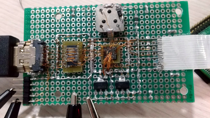
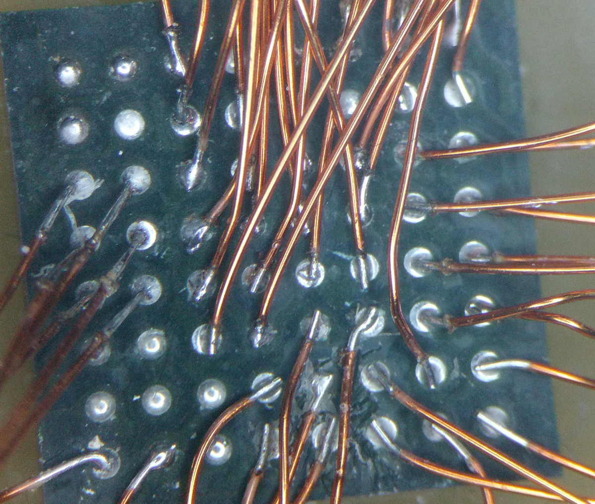
As the creator of Pi-KVM, [Maxim Devaev] needed to truly understand how the Toshiba TC358743 chip used in these capture devices worked, so he decided to build his own version from scratch. In the name of expediency, he didn’t have a proper breakout board made and instead decided to hand-solder the tiny BGA chip directly to some parts bin finds. The resulting perfboard capture device is equal parts art and madness, but more importantly, actually works as expected even with 1080p video signals.
 Ultimately, the lessons learned during this experiment will lead to a dedicated KVM board that will plug into the Pi’s expansion header and provide all the necessary hardware in one shot. As [Maxim] explains in the Pi-KVM docs, the move to the CSI connected Toshiba TC358743 cuts latency in half compared to using a USB capture device. That said, USB capture devices will remain fully supported for anyone who just needs a quick way to get things working.
This DIY capture card is a perfect example of how the skills demonstrated while working on a project can be just as impressive as the end result. [Maxim] didn’t set out to hand-solder a BGA HDMI capture chip, it was merely one step in the process towards creating something better. Those intermediary achievements are often lost in the rush to document the final project, so we’re always glad when folks take the time to share them.
[Thanks to Eric for the tip.]


I wish I was this mad. Bloody awesome work.
Holy heck, that’s awesome!
I’m certain I could solder like that too, if only I was a CNC soldering robot.
Now I feel like I want to try manual dead bug style BGA.. just to see if I can do it.. Could be cool for some circuit sculptures too I suppose, another thing I’ve wanted to try but never got around to it.
I have soldered QFNs for fun
https://www.instructables.com/id/ASIIC-ART/
and also did some tests with bgas. Best reuslts to use a wire that is weaker than the soldering joint. The coil of a dead chinese clock is a good source for thin wire.
I once did a BPM180 (Bosh air pressure and temperature sensor)
I did not much like the experience.
Later I bought a stereo microscope, doing it again now would probably be a whole different experience.
With a BGA it is easier than a QFN as the ball already contains solder. Touch thin wire against the ball, heat it, repeat. Obviously you will not break-out a 1000 pin 0.4mm BGA quickly this way, but a small chip is not a lot of work and quite simple, if tedious.
I draw the line at 0805/SOT-23. Maybe 0603 or LQFP if it’s an etched board. But this is bonkers.
Protip: an SOT-23 rotated 45 degrees lines up pretty well with an 0.1″ grid.
Used to work with a hardware guy who thought this sort of thing was easy. Awesome chap.
Sheesh! What is that? Like .5 or .4mm ball pitch? Helluva job!
I use 50mil breadboard all day long at work for doing prototypes for the nextgen GFCIs (btw the place I work invented that chip you will find in the last gen models that no one can figure out).
I thought I was hot stuff doing sot323 and 0603 passives, and have dead bugged chips with lead spacing less than 30awg wire, but just WOW. I am impressed. I never even considered doing BGA by hand.
I am completely humbled.
I guess I am now going to have to up my game.
I hope no one at work sees this article!
“I guess I am now going to have to up my game.”
Me too, lol!!!
Last week one of my employees milled out a part of a bga fpga and soldered directly to the substrate because a ball had been forgotten to connect. So it’s absolutely doable.
I’ve seen a photo of a big BGA chip soldered to the PCB with wires, it looked as if BGA chip had grown a system of roots made of red enameled copper wires…
On the other end of the spectrum two days ago I soldered some wires to fix my USB headphones mostly by feel and muscle memory. And the spacing between them was 0,1″. Poor eyesight is a huge problem for someone who enjoys electronics. I could either look very closely at the connection (less than 5cm or 2″ away) or solder it keeping my eye at safe distance. I’ll need to hack together some kind of camera-based magnifier. There are commercial solutions used by visually-impaired for book and magazine reading, but these are a bit expensive…
Might want to look into a jewelry magnifying glass?
https://www.amazon.com/jewelry-magnifying-glass/s?k=jewelry+magnifying+glass
They have rather narrow DoF range, and are designed for close inspection…
Also my cornea is deformed, causing multiple false images, refractions and other stuff that makes it hard to see. This is the main problem for me, actually. There is potential for transplantation, but the risk is too high. And my other eye is actually dead (killed by communism), so no backup for me. I was thinking about measuring the cornea deformation and creating a lens to counteract/compensate it, but there is the obvious problem of alignment. Such a device must either be placed perfectly on the cornea, or its position tracked and adjusted to the direction the eyeball is facing…
So I’m waiting for technological singularity and hoping that our future AI overlords would fix my eyes rather than killing me for being an useless waste of biomass…
Too bad about your cornea. I suffer from keratoconus which I suspect might be a lot milder than your problem. I use hard contacts with no correction – fitted to “bridge” the valleys on my corneas. Tear fluid fills the gaps. The contacts provide a “perfect” front surface. Though uncomfortable at first, they reduce the strange artifacts by about 90%. (Sorry to be off topic to the others in the comment section.)
Don’t apologise, I find this off-topic as interesting as the article personally. Both as a reminder that there are ‘strange’ conditions I’ve never heard of, causing issues I’ve never considered. And that despite those issue we all keep on trying and looking for ways to make things better.
How regular are both your vision problems? – I am wondering if the microscope type view port on the other end of a screen and/or optics setup to correct your visual aberrations could work – as those viewfinders force your eyes to be in a very constrained position negating alignment issues. So perhaps you could still get magnification and your visual problems at least reduced while you look through it.
(Warping of the screen image to counter how your eyes are buggered up or ‘standard’ corrective optics – the screen variant being an idea that might just turn into a good off the shelf assistive product – as high res screens and fast transform of images are relatively cheap now and you can keep tweaking it as your eyes change where ground optics are phenomenally expensive – though would give a better user experience.)
Foldi-One, I have only one eye, as the other was damaged by both glaucoma and oxygen poisoning in incubator, when I was born. As for the artifacts, they are contrast-based. While I’m writing this comment, light-gray letters create a ghost image that is transposed slightly to the left and down. I can get rid of it by moving my eyelid with a finger, which narrows my FOV. If I move away from the screen, the ghost image moves to the left even more. Bright point lights also create two semi-circular “rainbows” above and below the source, and bunch of rays sticking out to the right. Add to that near-slightness and glaucoma (which turns my eyeball into barometer – air pressure drops – eye pressure rises, sometimes causing eyeaches and headaches).
Moryc sorry to hear about the eye/headaches, that one I can really sympathise with as I have suffered enduring and quite debilitating headaches and photosensitivity for years (thankfully its much rarer now as I do seem to be getting better, but it was a most unpleasant decade (ish) that still comes round to get me sometimes).
Sounds like the microscope eyepiece type correcting for your visual problems should work reasonably well, creating a magnified image with a focal point close enough to your eye to minimise the ghost image (perhaps even limiting your FOV with a 3d printed eyecup – which would also position your eye in just the right spot as well). Obviously can’t fix all you visual problems but if you have a positionable camera and microscope camera you can feed into the screen based idea as appropriate you should (albeit with greater awkwardness) be able see what you are doing at your workbench well enough to tackle more challenging problems.
I’m not an optics or eye expert really – just a Maths guy with an interest in how everything works, but it looks possible to me. Not sure what the best starting parts would be to experiment with it if your interested, the phone screen, usb inspection microscope, any old high quality web cam or maybe interchangeable lens type camera for less zoom, and a collection of boom arm type things to position all the separate parts are to me obvious. The electronic brain could be almost anything (maybe even the phone the screen is built into?). Where I run out of ideas on best place to look for good parts is the optical parts, custom ground would be expensive, and even a replacement microscope eyepiece will need some optics between it and the screen – so it might be better to build your own based around the screen you end up with or select a screen based on whatever optics you can source.
Moryc just read another of your comments here – perhaps what you want is just something like a Pi with good screen connected to a DSLR with a good lens or two. That would be very like the reader device you used, and not that bad to build. Some sort of PCB clamp on an X-Y table underneath.
Going the DSLR route should allow zoom and autofocus to be simple to implement and being a DSLR change lens to one better suited when needed. gPhoto can do most everything you would want coupled with video4linux libraries (I’m told autofocus does work – but that I’ve never used – I have my cheap old cannon pointing at my workbench surface with fixed focus to snap that disassembly screw tracking shot etc).
Seems like it wouldn’t ‘fix’ your vision as much, but its really easy to do in comparison, and if that is enough to let you enjoy your hobby more then that is great! Its also a system you can put together the working concept easily to help improve you ability to create a better system
I had a very aggressive case of keratoconus, and both of my corneas were transplanted a couple of years apart in my 20s. Before then, I used rigid gas-permeable contact lenses–these fill up with fluid and even out the corneal surface (since they are rigid) and provided near-perfect correction for me, at least until my corneas became too cone-shaped for them to seat properly. My eyes are sensitive and it was extremely uncomfortable to wear both all day, but at least I could see. I eventually wore just one, which was more tolerable, until I got my transplants.
Anyway, my second transplant did not work quite as well as the first, which is now fully-correctable with glasses, so I understand the reluctance to do it with only one working eye. But if you haven’t tried the rigid gas-permeable contact lenses, you might find that they do exactly what your imagined compensating lenses do. They did for me, anyway, and if your eye isn’t degrading as fast as mine were, it could last you the rest of your life.
I have a USB microscope with excellent resolution but there is an enormous delay in the video, so much that it is useless for interactive work. I got a cheap loupe magnifier and now I can solder fine pitch smt devices with no problems.
Back in the school for the blind and visually impaired I had an access to the proper magnifier. It was an analog CRT system on a stand, in the base of the CRT part there was a camera and two lights. Underneath that there was a X-Y table with bearings to put a book or magazine on. There were controls for brightness, contrast, magnification, etc. The unit I used the most was B&W, with switch for inverting colors. I prefer dark background and light font for everything. That’s why I like Windows 10 – it inverts colors on demand…
Interesting, I have a friend who needs invert colours, and they hate windows 10 because its less consistent at staying in their mode than they found their previous OS (which I think might actually have been XP based but that I don’t remember).
Win10 has handy shortcut for that: [LCtrl]+[Win]+[C], which I use constantly, when I need to work with software or webpages with no dark mode…
The problem isn’t really the camera, it’s usually somewhere between the camera and your screen. Either you are going through a hub with other USB devices, or otherwise have a slow USB controller or something else going on. I also have an 1080p USB microscope, and I’ve had good and bad performance from it, but plugging it directly into my fastest computer is giving me quite usable results for ‘interactivity’ and specifically soldering tiny components.
Just some more BGA goodness:
https://hackaday.com/2011/03/13/reverse-engineering-the-psp/
http://jahonen.kapsi.fi/Electronics/Stuff/BGA_rework.jpg
Wow! I’m considering purchasing one or two of his boards when they are ready. It’s past time to put together a new home server and this will open up a lot more options for boards I’ll consider.
It would have also been awesome in a previous job for remote development.
QFN by hand isn’t terrible with proper board layout, you can (an)use the thermal pad by heating *through* the PCB.
I draw the line at bga though, I don’t hate myself enough for that. Majorly impressed every time I see it.
I’m more impressed by the fact this is one of the few projects that also supposedly emulates PS/2 keyboards.
But all source code for that seems to be in docker images…
Docker is only used for building and testing. Here the source code for pure arduino hid: https://github.com/pikvm/kvmd/tree/master/hid