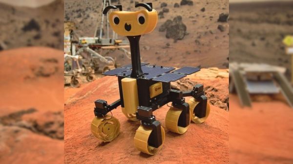
Over the past few weeks, a new season of Mars fever kicked off with launches of three interplanetary missions. And since there’s a sizable overlap between fans of spaceflight and those of electronics and 3D printing, the European Space Agency released the ExoMy rover for those who want to experience a little bit of Mars from home.
ExoMy’s smiling face and cartoonish proportions are an adaptation of ESA’s Rosalind Franklin (formerly the ExoMars) rover which, if 2020 hadn’t turned out to be 2020, would have been on its way to Mars as well. While Rosalind Franklin must wait for the next Mars launch window, we can launch ExoMy missions to our homes now. Like the real ESA rover, ExoMy has a triple bogie suspension design distinctly different from the rocker-bogie design used by NASA JPL’s rover family. Steering all six wheels rather than just four, ExoMy has maneuvering chops visible in a short Instagram video clip (also embedded after the break).
ExoMy’s quoted price of admission is in the range of 250-500€. Perusing instructions posted on GitHub, we see an electronics nervous system built around a Raspberry Pi. Its published software stack is configured for human remote control, but as it is already running ROS (Robot Operating System), it should be an easy on-ramp for ExoMars builders with the ambition of adding autonomy.
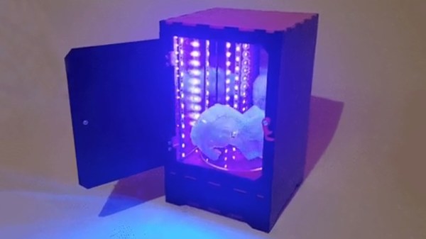
Resin printers have a lot going for them – particularly in regards to quality surface finishes and excellent reproduction of fine details. However, the vast majority rely on UV light to cure prints. [douwe1230] had been using a resin printer for a while, and grew tired of having to wait for sunny days to cure parts outside. Thus, it was time to build a compact UV curing station to get the job done.
The build consists of a series of laser-cut panels, assembled into a box one would presume is large enough to match the build volume of [douwe1230’s] printer. UV LED strips are installed in the corners to provide plenty of light, and acrylic mirrors are placed on all the walls. The use of mirrors is key to evenly lighting the parts, helping to reduce the likelihood of any shadows or dead spots stopping part of the print from curing completely. In the base, a motor is installed with a turntable to slowly spin the part during curing.
[Douwe1230] notes that parts take around about 10 minutes to cure with this setup, and recommends a flip halfway through to make sure the part is cured nice and evenly. We’ve seen other similar DIY builds too, like this one created out of a device aimed at nail salons. If you’re struggling with curing outside, with the weather starting to turn, this might just be the time to get building!
Signals and systems theory is a tough topic. Terms like convolution and impulse response can be hard to understand on a visceral level and most books that talk about these things emphasize math over intuition. [Discretised] has a YouTube channel that already has several videos that promise to tackle these topics with “minimum maths, maximum intuition.” We particularly noticed the talks on convolution and impulse response.
We think that often math and intuition don’t always come together. It is one thing, for example, to know that E=I times R, and power is I times E, but it is another to realize that a half-watt transmitter delivers 5V into a 50Ω load and that one watt will take just over 7V into that same load.
The example used is computing how much smoke you can expect to create by setting off fireworks. We presume the math models are notional since we imagine a real model would be pretty complex and involve things like wind data. But it still makes a nice example.
If you don’t know anything about the topic, these might not be the right ones to try to learn the basics. But we do applaud people sharing their intuition on these complex subjects.
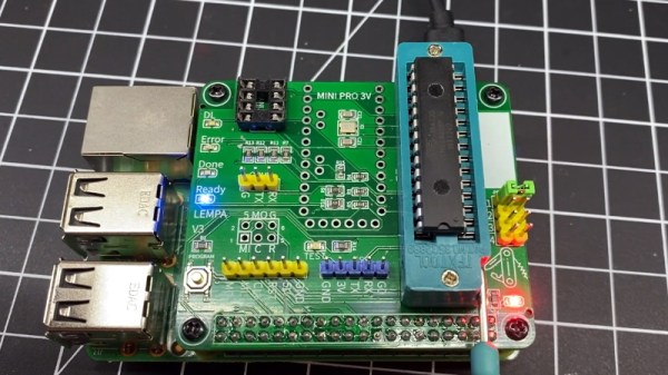
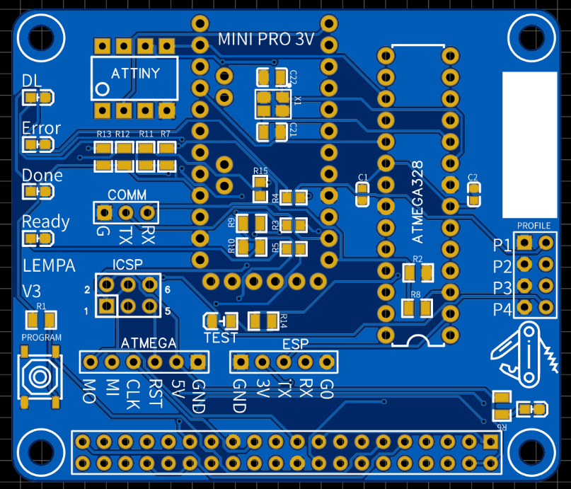
Once you graduate beyond development boards like the Arduino or Wemos D1, you’ll find yourself in the market for a dedicated programmer. In most cases, your needs can be met with a cheap USB to serial adapter that’s not much bigger than a flash drive. The only downside is that you’ve got to manually wire it up to your microcontroller of choice.
Unless you’re [Roey Benamotz], that is. He’s recently created the LEan Mean Programming mAchine (LEMPA), an add-on board for the Raspberry Pi that includes all the sockets, jumpers, and indicator LEDs you need to successfully flash a whole suite of popular MCUs. What’s more, he’s written a Python tool that handles all the nuances of getting the firmware written out.
After you’ve configured the JSON file with the information about your hardware targets and firmware files, they can easily be called up again by providing a user-defined ID name. This might seem overkill if you’re just burning the occasional hex, but if you’re doing small scale production and need to flash dozens of chips, you’ll quickly appreciate a little automation in your process.
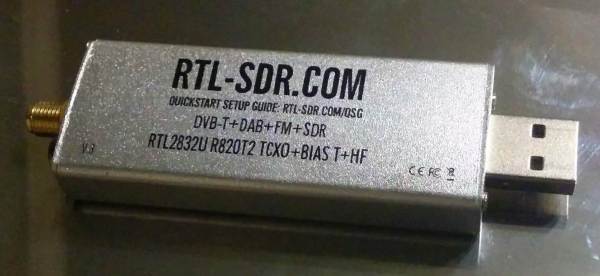
Measuring the performance of antennas in absolute terms that can involve a lot of expensive equipment and specialized facilities. For practical applications, especially when building antennas, comparing performance in relative terms is more practical. Using cheap RTL-SDR dongles and Python, [Eric Urban] was able to compare the performance of two shortwave/HF antennas, and documented the entire process.
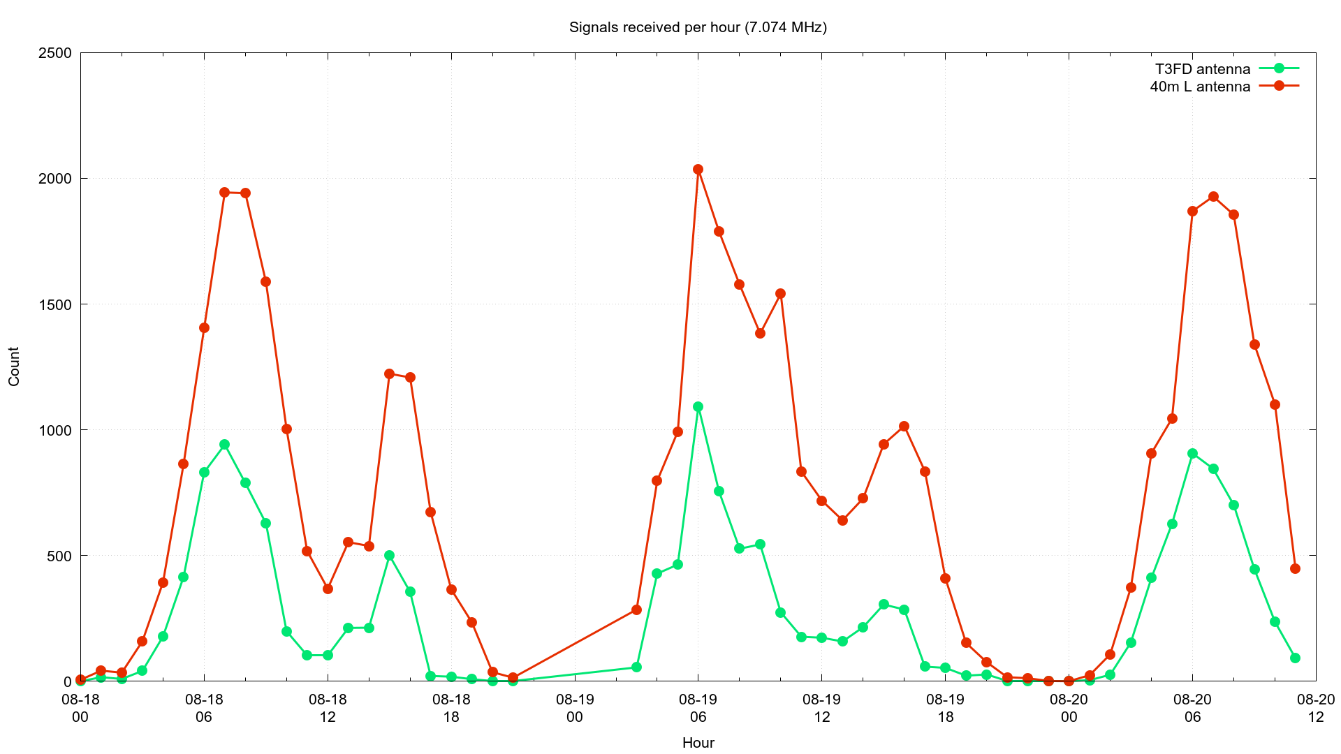
The two antennas in question was a single band inverted-L and smaller broadband T3FD antenna. [Eric] first gathered performance data for each over few days, connected to separate PCs with RTL-SDRs via low-pass filters. These were set up to receive FT8 transmissions, a popular digital ham radio mode, which allowed [Eric] to automate data collection completely. GQRX, a software receiver, converted the signals to audio, which was then piped into WSJT-X for demodulation.
Data for each received FT8 transmission was recorded to a log file. [Eric] also modified GQRX and WSJT-X to give him all the remote control features he needed to automatically change frequencies. Between the two antenna setups, more than 100,000 FT8 transmissions were logged. Using the recorded data and Python he compared the number of received transmissions, the distance, and the heading to the transmitters, using the location information included in many FT8 transmissions. Where the same transmission was received by both antennas, the signal-to-noise ratios was compared.
From all this data, [Eric] was able to learn that the inverted-L antenna performed better than the T3FD antenna on three of the four frequency bands that were tested. He also discovered that the inverted-L appeared to be “deaf” in one particular direction. Although the tests weren’t perfect, it is impressive how much practical data [Eric] was able to gather with low-cost hardware. Continue reading “Comparing Shortwave Antennas With RTL-SDR And Python”→
“Keep it simple” sounds like such good advice, but what exactly is the “it”; what parts of a project should you try to keep simple? You can’t always make everything simple, can you? Are all kinds of “simplicity” equally valuable, or are there aspects of a design where simplicity has multiplier effects on the rest of the project?
I ran into two seemingly different, but surprisingly similar, design problems in the last couple weeks, and I realized that focusing on keeping one aspect of the project simple had a multiplier effect on the rest — simplifying the right part of the problem made everything drastically easier.
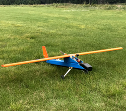
The first example was a scratch-built airplane design. I’d made a few planes over the summer, focusing on plans on the Interwebs that emphasize simplicity of the actual build. Consequently, the planes were a bit heavy, maybe not entirely aerodynamic, and probably underpowered. And this is because the effort you expend building the plane doesn’t fundamentally have anything to do with flight. Keeping the build simple doesn’t necessarily get you a good plane.
Weight, on the other hand, is central. Wings produce lift, whether measured in grams or ounces, and anything heavier just isn’t gonna fly. But reducing weight has a multiplier effect. Less weight means smaller and lighter motors and batteries. Structures don’t need to be as stiff if they’re not subject to heavier bending forces. And, important to the noob pilot, planes with less weight per wing area fly slower, giving me (ahem, the noob pilot) more reaction time when something goes sideways. Trying to simplify the design by trimming weight has knock-on effects all around.
My latest fully-DIY design threw out anything that brought weight along with it, including some parts I thought were necessary for stiffness or crash resistance. But with the significantly lowered weight, these problems evaporated without needing me to solve them — in a way, the complexity of design was creating the problems that the complexity of design was supposed to solve. Ditching it meant that I had a slow plane, with simple-to-build wings, that’s capable of carrying a lightweight FPV camera. Done and done! Simply.
Nope. Too complex.
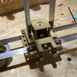
At the same time, I’m building a four-axis CNC foam cutter. I’ve built many 3D printers, and played around with other folks’ DIY CNC machines, so I had a few design ideas in my head starting out. My first iteration of an XY axis for the machine runs on metal angle stock with a whopping eight skate bearings per axis. It’s strong and rigid, and clumsy and overkill, in a bad way for this machine.
3D printers want to move a relatively light tool head around a small volume, but relatively quickly. CNC mills need to be extremely rigid and shoulder heavy side loads, subject to some speed constraints. A foam cutter has none of these needs. The hot wire melts the foam by radiation, so there are no loads on the machine because it doesn’t even contact the workpiece. And because it cuts by melting, it has to go slow. These are the places in the design where simplification will bear the most fruit.
I write this in retrospect, or at least from the perspective of a second prototype. I wanted the first design to hold the cutting filament taut, hence the rigid frame. But separating the tension from the motion, by using a lightweight external bow to keep the filament tight, meant that the machine could be dead simple. I could use smaller plastic sliders instead of complex bearings, on thin rods instead of bulky rails. In a day after having this realization, I got twice as far as I had on the previous machine design in a week, and it takes up a lot less space in my basement.
So take your KISS to the next level. Brainstorm a while about the binding constraints on your design, and what relaxing any of them can do. Do any particular simplifications enable further simplifications? Those are the ones that you want to start with. Keep it simple, smartly. And because it’s not always easy to find these multiplier effects, tell your friends!
This article is part of the Hackaday.com newsletter, delivered every seven days for each of the last 200+ weeks. It also includes our favorite articles from the last seven days that you can see on the web version of the newsletter.
Want this type of article to hit your inbox every Friday morning? You should sign up!
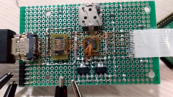
If you’re developing a performant IP-KVM based on the Raspberry Pi, an HDMI capture device that plugs into the board’s CSI port would certainly be pretty high on your list of dream peripherals. Turns out such devices actually exist, and somewhat surprisingly, are being sold for reasonable prices. Unfortunately the documentation for the chipset they use is a bit lacking, which is a problem if you’re trying to wring as much performance out of them as possible.
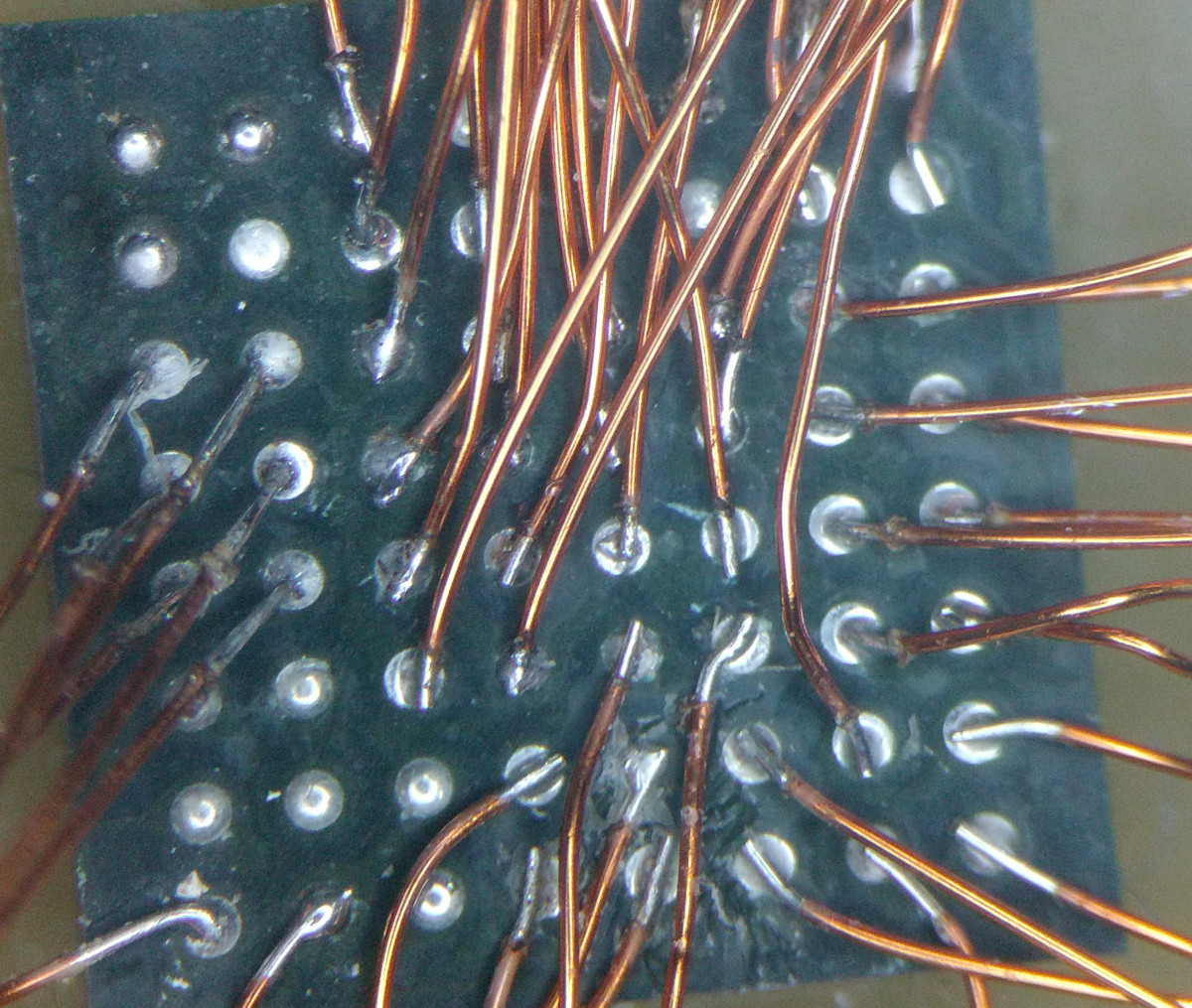
As the creator of Pi-KVM, [Maxim Devaev] needed to truly understand how the Toshiba TC358743 chip used in these capture devices worked, so he decided to build his own version from scratch. In the name of expediency, he didn’t have a proper breakout board made and instead decided to hand-solder the tiny BGA chip directly to some parts bin finds. The resulting perfboard capture device is equal parts art and madness, but more importantly, actually works as expected even with 1080p video signals.
Ultimately, the lessons learned during this experiment will lead to a dedicated KVM board that will plug into the Pi’s expansion header and provide all the necessary hardware in one shot. As [Maxim] explains in the Pi-KVM docs, the move to the CSI connected Toshiba TC358743 cuts latency in half compared to using a USB capture device. That said, USB capture devices will remain fully supported for anyone who just needs a quick way to get things working.
This DIY capture card is a perfect example of how the skills demonstrated while working on a project can be just as impressive as the end result. [Maxim] didn’t set out to hand-solder a BGA HDMI capture chip, it was merely one step in the process towards creating something better. Those intermediary achievements are often lost in the rush to document the final project, so we’re always glad when folks take the time to share them.