Bullet time became the hottest new cinema effect after it burst on the scene in The Matrix (1999). Back then, the cutting edge special effects required serious hardware and serious processing power to do the job. These days, of course, things have moved along somewhat. [Eric Paré] is no stranger to a high-end setup, but wanted to see what could be done at the lower end of the market. (Video, embedded below.)
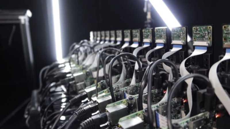
Rather then relying on a bank of expensive DSLRs, [Eric] decided to try building a bullet-time camera rig out of 15 Raspberry Pis, and the standard Raspberry Pi Camera. Whereas just one camera in one of his professional setups may cost well over $1000, this entire rig was likely built for less than that in its entirety.
Initial results were jerky and unappealing, but [Eric] persevered. One of the biggest problems was inaccuracy in the camera assemblies, as they were stuck on with thermal paste. With some custom mods and tweaks, [Eric] was eventually able to get things to a passable state. It also has the benefit, compared to a DSLR rig, that the cameras can be mounted much more closely together due to their small size.
Work is already underway to upgrade the rig to the new Raspberry Pi HQ Camera, which we’ve discussed before.
[via DIYPhotography.net]


I helped develop one of the first rigs that did this (ReelEFX Multicam https://www.reelefx.com/multicam-list) – It’s one of those great “simple in concept” (Eadweard Muybridge did it with glass plates and threads for trip wires) but “hard in practice”. We did it initially with film SLRs.
What you find is that there’s a surprising variation in the lenses, even in mass production. If you have one camera, you won’t notice if the lens has a slight color cast – when you print from the negative (or these days, render the image) – typically the image is “white balanced”. But when you have 100 different cameras, you find that they all have a slightly different color cast, which you have to then correct out somehow (a target in the scene that can be cropped out helps).
Same thing with geometric alignment – each lens is slightly different in terms of the ray paths, so even if they’re all pointed the same way, you’ll need to “stabilize” the resulting video. Angular displacements aren’t too tough if there’s decent camera/subject distance (because you can just shift the image), but if you’re close to the subject, then the “view point” might be wrong, and that’s a tougher geometric correction.
But once you get it working, you can have a heck of a lot of fun and do really neat things.
BTW the “GAP swing” commercial and the Matrix Bullet Time were done with CGI to interpolate between standard movie camera footage.
Early use of the multiple camera rig were a Nike commercial with Andre Agassi, a Lexus commercial with a girl on a scooter, and the movie Spy Kids –
There are tools for automagically color matching photos and/or videos. As for lenses, one could take a sample photo with each one and create a correction profile for individual lens…
I wonder if the bullet time effect could be achieved with fewer cameras, by doing more post-processing and recreating missing frames the way some time warp/slow mo algorithms generate frames between frames…
Alternatively just photoscan your actor and make a 3D animated character for the shots….
This is the answer: With more and more backgrounds/sets being completely digital and actors being creepily more so, the rest is just a matter of time and budget-trimming.
Now if we could make the actors more believable when they are off camera…
Well this gets to the heart of the “art” argument. The Nike commercial was shot by a director (Tony Kaye) who doesn’t believe in CG, and he wanted a tracking shot that followed the tennis ball down the court. Putting a ball on a green stick in front of a green screen, and then comping it into the shot would have been trivial (even in the 90s, when that was done).
With a multicam rig, you might do color correction and cropping on each frame, but you’re still actually capturing sequential (or simultaneous) images in a virtual motion picture camera – something that has been done for 100 years. That’s pretty different from a very well done computer model with mocap and image mapping.
There are also shots that are inherently hard to do with CG – rain is one of them. If you want to do a 360 pan around the talent, freezing time in an instant with raindrops falling down, that’s hard to do in CG – but trivial in multicam. (Spy Kids in 2001 had a shot like that, with a sprinkler). Coolio had a music video where the multicam rig was used to stop motion and pan in some significant points in a story of a kid’s growing up.
The multicam was used in Swordfish, in the explosion scene – it’s hard to CG people flying through the air with explosion debris, but the multicam does a nice job. (https://www.reelefx.com/effect.153) A similar one in a public service message about terrorism.
In other cases, it’s used for the visual impact, and CG would probably work just as well.
You can probably overcome the mounting method for the pi camera by using its own PCB as a spring to push the lens assembly into the mounting plate. I have a few of the old cameras and have done so just fine, but never tried to do anything like this with them – it was just the mounting method I used (and did notice the camera shifting slightly as it was tightened down).
That said HQ camera has to be the way to go now – cheaper than DSLR by a pretty big margin, and good mounting option (yes you can get cheap older DSLR with good sensors – but you still need all the lens and mounting, batteries etc – the required support stuff adds up fast).
I wonder if the compute module would be a better choice – having the two camera channels available would reduce the number of Pi’s and cost of the rig without impacting its function I would think. Design and send out for a PCB with 8 or so compute module slots, the networking chips onboard so just the camera lanes and a few control pins for flash and buttons off the board. Probably get some interest in any spare boards for cluster computing too.
Still its a damn neat concept, impressively compact and I like the control panel very sensible, and looks well organised.
This. I was thinking the stereo pi would be good a good platform for something like this.
Now boost them up with machine learning a-là lego stop-motion article we’ve read a couple of weeks ago.
Hello, There is an effect where the person is stationary however the back ground rotates back and forth which creates a 3D effect. Can someone tell me what that effect is called or how it is done. Thanks
That’s just “bullet time” across the cameras backwards and forwards across the same instant. That’s kind of the essence of the thing. You’re in the right place.
Excellent, thank you very much for responding. :)
Exactly what’s being described here. You essentially define the camera motion by where the cameras are placed, and the frame rate is determined by when you fire the cameras. The easy one is where you put the cameras in a circle and fire them simultaneously, so you get what looks like a pan around the subject in frozen time. But a better use is to ramp in and out, so motion doesn’t just “stop” it slows gradually, and then returns to normal gradually – You can also fire multiple frames from the same camera, to get motion video from a fixed point in the trajectory.
it’s ultimately a creative tool.
Wobble vision
But how were the cameras synchronized? As I understand it the RPi camera sweeps the image from top to bottom so it needs to do it fast, but the sweep also should start at the exact same time on all the cameras, with the same timing settings etc.
Enough to just broadcast a packet over the network, have all RPis share the same settings and that’s it? Is each frame synchronized separately? The video is missing the important stuff :).
I had exactly this question. How is frame synchronization performed?
If the cameras are recording video, they need to be frame-synced and exposures paced at integral frame counts.
If they are running in snapshot mode, they still need sub-millisecond timing accuracy, maybe even to a few microseconds.
I don’t see a sync cable running around there, so it’s up to the non-deterministic timing of Ethernet, but NTP is too imprecise.
The only way I can see this working is using PTP to run them all on the same timebase, then figuring out how to trigger the camera module with sub-millisecond jitter — you can’t depend on just using the camera internal clock and grabbing the next frame. Each camera would then be given a script on when to trigger.
I can do microsecond-precision triggering on a cheap “scientific” USB camera using an external trigger line (not good enough to do time-of-flight though), but I don’t know enough about the Pi camera system to know whether you can do that internally to the Pi. It would be very, very neat to be able to. I’d have a ton of uses for it.
I don’t think the Pi’s are recoding video – they are each snapping one still photo when Eric presses the Bluetooth clicker in his hand. The still photos are stitched together to create the “bullet time” view. It seems like the custom software that is controlling all of the Pi’s is sending a broadcast packet when Eric triggers the clicker. If you watch the video closely, the Ethernet activity LED flashes once on every Pi at the same instant when the photo is taken. Pretty ingenious solution. :-)
Hey Scott!! You are right, we’re snapping still! Thanks for your comment (thank you Jim also!!!), that pushed me to provide more details about the process. I updated the blog post. Scroll at the bottom of the page for a long explanation: https://xanglecs.com/blog/bullet-time-photography-using-raspberry-pi-cameras
That’s exactly how you do it. You load a sequence into the camera, and they fire according to the script. In this kind of network, where you control all the traffic, getting 10s of microsecond sync is pretty easy without using PTP. You don’t even need NTP (except to set the clock), you can send a broadcast IP datagram that effectively says “start now” – the trick is in understanding the latencies in the ethernet stack in the PI, so that all the threads running are in the same state, so the latency between “receive packet interrupt” and “start timer” is consistent.
Running a microcontroller, you’d just put it all in the same Interrupt service routine. You send a message to all saying “the next packet is the sync” – that “arms” the ISR, and the next packet starts it off.
There are, of course, details like distributing through switches, etc.
However – when we were doing this stuff on set – you really don’t want to have a separate cable to each camera – because then you need hundreds of cables, which take time to setup and install, etc. – You’ve not lived til you have to setup (and teardown) 100 cables that are 50-100 feet long. Remember that on-set, time is very much money.
What you want is an RF network, but not Wi-Fi (which would be too easily interfered with) You could do WiFi to manage the system, with acknowledgements from each camera that it was configured, but the sync and timing would be done by a dedicated RF channel of some sort. Then all you worry about is batteries. and not cables.
Could use LoRa RF radio to shutter release. Could enable cloud bullet time with a one mile across line of cameras ;D
I would be leery of any RF based approach in the ISM bands – you’re competing for spectrum with other users, so you’d risk having your camera trigger jammed by some other user at “just the wrong time”. This is notwithstanding LoRa’s use of spread spectrum techniques.
LoRa is really a “data comm” system for low rate (18 bits/sec to 40kbps) data transmission, not a “timing” system. the commercially available parts that implement LoRa may not have sufficiently deterministic timing between digital interface and “over the air”. It might be ok, it might not. But realistically, you only need 100 meter sorts of ranges, and there’s lots of simple, easy ways to do the time synch.
Since it is a camera system, one could also use optical techniques for sync
A very good question, though I don’t think it matters all that much – unless you are trying to capture very fast moving targets.
My bet would be they are all syncing to the same network time server and then counting down to capture at a specified time. So if you resynced recently the error will be almost zero across all the Pi as the clocks can’t drift that badly and the zero point won’t be that far off either..
That is the hard part. On the original rig, with film cameras, we used a digital sequencer to send the pulse to the remote jack on the camera. Literally miles of cables. The problem we found was that modern cameras have a microcontroller that “polls” the remote trigger, so there was jitter. So on the next revision, we replaced some of the camera electronics to directly fire the shutter (after all, you don’t need autofocus or autoexposure). Still miles o’ wire.
The next iteration after that was a specialized serial interface where we would program each camera to fire on selected pulses of a common sync line. Camera 1 would fire on pulse 1, camera 2 on pulse 2, etc.
I left before the latest DSLR versions came in so I don’t know what they’re doing now, but network interfaces with good timing would work.
Realistically, you need to have sub-millisecond timing, or the motion looks jerky. At 24 fps, you’ve got about 41 milliseconds between frames, if the jitter is 1 ms, that’s 2-3%, and depending on the scene you’ll notice it (that’s why “fire simultaneously” is popular – it’s easy).
Getting 10s of microsecond timing over something like NTP on a “private” network would be straightforward. The key would be in synchronizing the camera hardware – but most camera chips do have some form of electronic shutter control. Considering that pretty much every USB device out there can adequately synchronize 8kHz (125 microsecond) audio samples accurately, the hardware exists, but sometimes, the software interfaces are pretty tricky.
Another interesting “bullet time” example by Toshiba. https://youtu.be/gA8GM6HdvJA
There is a brief description of the process they used here: http://archive.themill.com/portfolio/1737/time-sculpture?q=Toshiba
This is not new: also try adding DAINAPP to increase the frame rate and increase the distances between cameras
https://hackaday.com/2020/09/20/boost-your-animation-to-60-fps-using-ai/
https://www.patreon.com/DAINAPP
https://youtu.be/o97dGA3qoVM