It’s a safe bet that most Hackaday reader’s interest in electronics started at a young age, and that their early forays into the world of hardware hacking likely involved some form of “playground” kit. As long as you didn’t lose any of the components, these kits promised the user that hundreds of possible projects were just a few jumper wires away. Extra points awarded for when you decide to toss away the manual and fly solo.
While there’s still no shortage of such products on the market, [Josh Kittle] felt the concept could do with a freshening up. His open hardware “Microcontroller Trainer” harkens back to those old multi-kits, but adds in the sort of high-tech gadgetry that makes the modern DIY world go round.
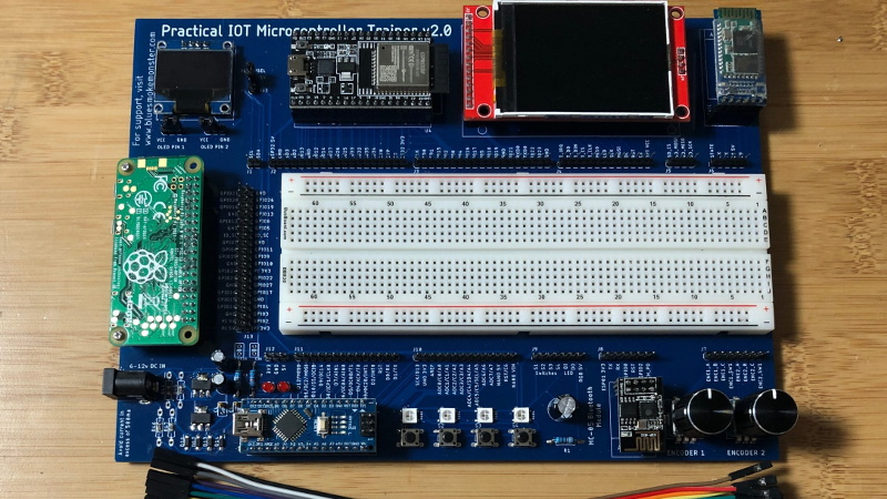
 It’s still got the traditional layout: a center mounted breadboard surrounded by an array of LEDs, a handful of buttons, and a pair of potentiometers. But there’s also sockets for the Raspberry Pi, ESP8266, ESP32, and Arduino. Plus a few of their most popular friends to keep them company: a .96″ OLED, 2.4″ Touch TFT, and a BC05 Bluetooth module.
Originally [Josh] created this design to help clean up his own workspace, figuring he could just put his most used components on a single compact board. But as you might expect, others expressed interest in the concept. Now he’s producing them as kits, and even working his way towards a third hardware revision that adds features such as an integrated 18650 battery for portable use.
While electronics kits that have you build a functional device are a great way to learn the ropes, we’re always glad to see fresh takes on the classic electronic “playground” concept.


That looks like a great way to start into Electronics. Also, just a very handy development system.
I’m the creator – Thanks for commenting. One individual bought two kits so he could prototype ‘both ends’ of a wireless communications system. I thought that was a cool idea.
Can you tell us where your open source trainers are available in part or complete and at what costs
Very cool. Add an HDMI screen and a USB keyboard and use the Pi to develop for all the micros. One-stop shop.
Was interested. But needing to work with some surface mount parts is a non-starter for me. Sorry.
Problems with the eyes or hands? I’m near sighted an after trying my first smd i never looked back. Sharp tweezers and no coffee in the morning and someone is your relative. Just start with 1206 and workt your way up to 0603.
“and someone is your relative.”
Love it!
“Just start with 1206 and work your way up to 0603.”
Don’t you mean, “work your way down”
B^)
I don´t see any. I see a big PCB but the rest is just connectors to commercial modules. I wish china would pick it and mass produce such a board. Even unpopulated.
The power supply part. Not that surface mount is anything to be scared of.
Chuck, thanks for the feedback! I’m the creator of the project: I would be happy to send you a kit with the SMD work already done if it helps me get a kit into the hands of somebody who would enjoy it. Just leave me a note in the ordering page to let me know!
+1
I remember in the 60’s Allied Electronics had something like this concept – a PCB with the parts around the edges, space for an index card in the middle, jumper points around the edge of the card space and the card had point to point wiring on one side, and a schematic on the other.
I never saw one of those.
Interesting concept though!
Kit like this was the foundation of the “Blacksburg Group” and a staple part of the EE programs at Virginia Tech.
E&L Instruments became a spin-off, producing various “outboards” and Design Kits like the MMD-1. These later became part of Global Specialties, and survived and evolved until quite recently.
The kist were also the foundation of the original “Bugbook” series by Dr. Peter Rony, Dr. Jon Titus, and Dr. David Larsen.
It’s lovely to see someone thinking along these lines. We would do well to update the material and kits of the original Bugbooks, and launch a whole new generation into electronics and computing…
Don’t forget, Jonathan Titus created the Mark 8, the 8008 based computer featured in the July 1974 issue of Radio Electronics.It
I ended up with a set of Bugbooks about 1977. Around them awful. They were designed for a university course, not for a hobbyist. There wasn’t much to extract if you weren’t following along. There were way more useful books.
Like this – very neat. Our corporate dev boards are similar – loads of IO round a central socket which you can plug one of our chips (and support gubbins) into.
Would be nice if a “microBus” connector could be added also: https://www.mikroe.com/mikrobus. (note: I am not affiliated with them but I used clock boards from this company and found them being high quality.)
They also have microBusArduino converters.
I love this idea. I was not familiar with this, but just checked it out. I like the design of their bus, especially the dual power rails built in. Thanks for sharing!
I am a member of a group of semi-retired engineers that have taught two courses per year (basic electronics and embedded systems) for the last 12 years at a local parochial school. For a more formal educational environment, this is less than optimal, and should not be considered ‘typical’ for electronic, electrical, or embedded systems education. It does appear to be suitable for the hobbyist bench, or perhaps for the tutorials done in ‘maker’ shops.
Brian,
Thanks for taking the time to comment. I’d love to hear what changes you would make to optimize this for a classroom environment. I can probably guess that different families of devices are likely targeted, but I would love to hear your thoughts.
Josh
“It’s a safe bet that most Hackaday reader’s interest in electronics started at a young age, and that their early forays into the world of hardware hacking likely involved some form of “playground” kit.”
Or taking apart everything in the house.
What’s that? Putting back together? Perish the thought.
I may be guilty of taking things apart as a kid.
When I worked at a radar base, some of my cow-orkers would reminisce about a former employee known a “tear it apart!”…
1 more suggestion. A level shifter so the 3V and 5V micros can talk directly.
You know, I hadn’t considered projects with the microcontrollers talking to one another. Great point! Thanks!
Great looking board – These are the main parts I use as well so it would be great to have things nice and organized.
A 50-in-1 electronics set with the cardboard-mounted components and spring connectors was a key part of my teenage education in the 70s. About 10 years ago I bought a 300-in-1 set with the central prototyping area, out of nostalgia, and because I wanted to make a better-equipped area for experiments. So I’m very much onside with the concept. I even modded it heavily with a power supply, LED bank, alphanumeric display and other enhancements.
But to tell the truth, I hardly ever use it. For working with ESP and Arduino boards, I have several custom jigs made up, and often, one only needs the board and a USB cable to be up and running anyway. If I’m doing something with discrete components, it takes less desk-space to just grab a single small prototyping board.
Possibly just the bad habits of an old nerd. Anyway, the featured board is possibly the best implementation of a microcontroller/single-board-computer workspace/playground that I’ve seen. Well-done! Suggestion – you could probably get by with a half-size protoboard, which would leave more room for accessory devices.