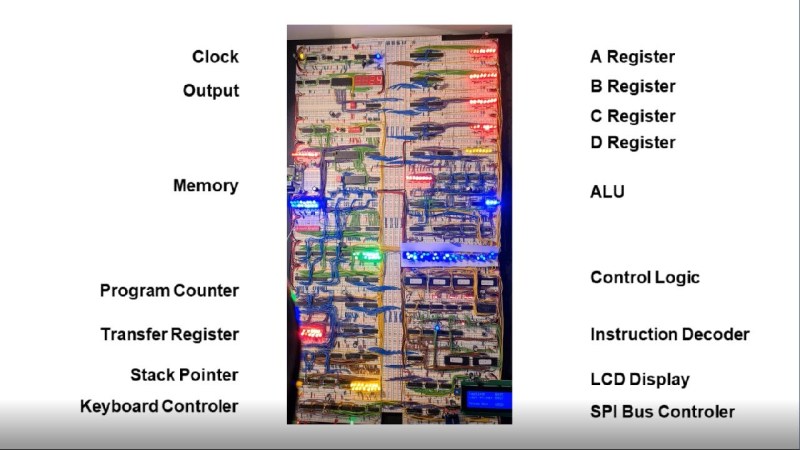
Getting into a big electronics project often involves the use of specialized tools, namely the use of some sort of soldering iron or other way to apply solder to often intricate, tiny, and heat-sensitive parts. While it’s best to learn to pick up this skill at some point, it’s not always necessary, even for big, complicated projects like [DerULF1]’s full 8-bit computer that he built entirely on breadboards.
For a fully featured 8-bit computer, this build goes deep into the details of how the computer works. The clock allows programs to be stepped through one cycle at a time, and even the memory can be individually accessed with a set of switches. There are plenty of other interesting features as well, such as using registers to access extra memory. It features an SPI port and PS/2 keyboard controller and also loads programs from an SD card.
The build was inspired by some of [Ben Eater]’s projects which famously focus on using logic gates and TTL chips to perform complex tasks, such as another breadboard computer which plays snake on a small display. It’s certainly a great way to learn about the inner function of computers, and better still that no soldering is required. But you may need a few extra breadboards.
Thanks to [Duncan] for the tip!


Given how failure prone some breadboard contacts are this would be a hell to hardware debug.
I wouldn’t try this myself, even with the wiring 100% correct i’d still have something not work.
Cheers to DerULF1!
Yikes. I even have little niggles when working with small breadboard projects! I wouldn’t try this myself either.
Hats off to the tenacity of the builder…. Congrats to getting a working project!
There is an unbelievable difference between a brand name $10 BB830 board and a $2 look-a-like, a lesson I learned from my own Ben Eater CPU build.
While my system is simpler than the one here (only 16 boards) the Bus Board brand gave surprisingly few and rare connectivity problems. 5.0v regulated into the top-left, and still reading 4.95v at the bottom-right.
The cheap boards however are a much different story! You can actually feel the clips inside deforming and ‘snapping’ apart when a lead is inserted. It was almost certain that clip would never make reasonable contact with anything else inserted in the future, and if the lead isn’t kept perfectly 180 or 90 degrees, wouldn’t maintain contact with the first inserted part for long either.
They might feel like you’re saving money, but the reality tends to be either tossing the things and buying brand name boards (wasting whatever was spent on the cheap ones), or accepting the insanity and random behavior to come.
I basically don’t breadboard at all these days. It’s a lot of work, and doesn’t catch a major source of errors, which is schematics not saying what you think they do, unless you’re extremely careful and have some kind of cross-check process between breadboard and CAD.
I’m not entirely sure what kind of issues I’d even be looking for on a breadboard that a simulator wouldn’t find.
But maybe they get more valuable when you do more analog stuff or discrete logic.
Very nice job!
Great job.
I would love to get a pcb of this.
What a lovely piece of work.
I would be frightened – one wire falls out – but where does it belong?
Debugging, ok. Found a little one on the description Control(l)er ….
This is just another nudge to do one implementation myself …
As people here will know, Burkhard Kainka went in a different direction:
Have as little components as possible:
3 switches, 5 LEDs and a Micro and a battery basically.
No PC, no Assembler, no comiler, no linker – just your brain
And neverteless you can start programming – all is in 4 bit, all in HEX nibbles.
I got this TPS bug about 6 years ago.
A new kit came out this year, and I wondered, if you could save on even more
– actually ALL OF IT.
Programming and do it all on paper. It works.
Have fun, lokking through the facebook page where I posted a few extensions of Burkhard’s project
https://www.facebook.com/groups/269499491046124
“I would be frightened – one wire falls out – but where does it belong?”
The build tends to make you intimately familiar with every last bit and signal in the system, not just the end result but the effect each and every component, IC, and gate has. A disconnected wire is one of the easier things to debug.
Going the other route you mention is the main problem with the disconnect. That micro for instance is a pretty huge “black box”. What would be the end result of a disconnect between say “b register output enable” and the microcode?
How many sections of code make up that wire? How many other parts will fail without it?
A hardware build can let you step through each microcode stage within each clock cycle, to get right down to seeing the ‘BO’ signal high yet the B register contents not showing up on the data bus. and right there you see it must be the wire connecting those two!
Hopefully if nothing else, this may serve as a nudge++ for you
Having seen the video now, I am even more impressed. Congrats to this successful project.
This is very well done- you really didn’t cut any corners. I’ve been a hobbyist for about 50 years and can only think of one or two times when a solderless breadboard had an intermittent or a short unless I’ve abused it. Keep the wire size around 24-26 and they are very good.
“Nothing is done, if Tetris won’t run.” – Love it! Very well done project (and slick horizontal LCD Tetris).
I must be the last hobbyist still building prototypes in wire-wrap. I know, because wire-wrap is the last thing Fry’s still has in stock.
Seriously, wire wrap sockets on perf-board gives you a durable board. You can easily make changes and correct mistakes. No heat involved.
You can design the whole layout as a PC board on 0.1″ grid, print it out on paper (mirrored), stick it on perf board, and start wire-wrapping. If you need SMD components, you put those on adaptors with long pins. You can poke in resistors, caps, LEDs, and wire to their long leads, or even solder them together, dead-bug style.
Sockets can be expensive, but for $20 you can get a hand tool and one color of wire (I use red, black, blue, and yellow). Altex Electronics carries them in store, as do the major distributors. It’s a big harder to obtain automatic tools, but you can find bargains on used guns.
Wire wrap is the home method in which you can easily make equal length trace pairs. Connections are corrosion-free and will last decades in service.
https://www.nutsvolts.com/magazine/article/wire_wrap_is_alive_and_well
https://hackaday.com/2018/05/04/ask-hackaday-whatever-happened-to-wire-wrapping/
I am doing a video series on implementing Ben Eater’s 8 Bit Computer in an FPGA on my YouTube channel for anyone who is interested: https://youtu.be/IdU7fcyGl9U