One of the very first examples for an MCU or SoC usually involves the famous ‘Blinky‘ example, where an LED is pulsed on and off with a fixed delay. This is actually a lot more complicated than the ‘Pushy‘ example which we looked at in the first installment of this series. The reason for this is that there’s actually quite a story behind a simple call to delay() or its equivalent.
The reason for this is that there are many ways to implement a delay function on a microcontroller (MCU), each of which comes with their own advantages and disadvantages. On an STM32 MCU, we get to choose between essentially an active delay (while loop), one implemented using the SysTick timer and using one of the peripheral timers. In the latter two cases we also have to use interrupts.
In this article we’ll take a look at all three approaches, along with their advantages and disadvantages.
Recapping the Basics
In Arm MCU architectures, generally the same Cortex-M processor core is used within the same family of MCUs by a manufacturer such as ST Microelectronics (‘ST’). This core is connected via a variety of AMBA (Advanced Microcontroller Bus Architecture) buses, with AHB being the fast bus. AHB connects the core to all peripherals that need the low latency and speed, such as RAM, ROM, GPIO banks and display controllers.
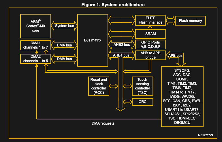
Meanwhile the slower APB connects peripherals that are fine with less bandwidth and lower speeds, which includes the I2C, timers, USARTs and SPI peripherals. In the Pushy example, the processor core would constantly query the GPIO peripheral’s incoming data register (GPIO_IDR) and write into the outgoing data register (GPIO_ODR) depending on those input values.
Enter Blinky
In the case of the Blinky example, we remove the active polling of the GPIO_IDR that was used to read the button input, instead relying on the delay function that is added. Whenever we return from this blocking delay function, we toggle the GPIO_ODR bit, which causes the LED that is connected on that pin to be lit or not.
The code example as implemented using my Nodate framework thus becomes:
[gist https://gist.github.com/MayaPosch/bcc02c9e35dd8f825cb0c6398089db9a /]
This example defines a few presets for different boards, with here the ‘Blue Pill’ (STM32F103C8) version used. We won’t cover the GPIO module here again, as the used GPIO functions in this example were already explained in the first article in the series. Feel free to have a look at it if you need a refresher, though.
Our focus will be on the Timer module instead, the way its delay() function is implemented, as well as the two alternate approaches.
The Low-Tech, Active Delay
A completely serviceable, functional, and reasonably accurate delay feature can be implemented in a bare-metal environment using nothing more than a humble while() loop. This exploits the discrete nature of processor cycles in combination with knowing the current system clock. Essentially this means converting the desired delay to processor time and counting down (or up) to that interval.
Assume the MCU (SysClock) is clocked at 48 MHz. If we want to delay with microsecond resolution, we need to multiply the μs interval value with 48 to get the target number of clock cycles we wish to wait. Naturally, each iteration of the while() loop takes more than one clock cycle, so we then have to divide the number of clock cycles by the duration of a loop iteration. Say it takes 4 clock cycles for one loop iteration, we get:
int count = (usecs * 48) / 4;
while (int i = 0; i < count; ++i) {
    count--;
}
Obviously, this is a rather easy way to implement a delay function, once one has calculated the appropriate parameters. As with many things in life, when something is this easy, it has to come with a whole list of gotchas. In the case of this delay function one doesn’t get disappointed in that regard.
First and foremost is its lack of accuracy. Even if we didn’t use integer values to calculate the appropriate clock cycle interval, there is still the unavoidable weakness in that this function fully runs on the (single) processor core. The moment a single interrupt occurs (e.g. from a timer, USART, I2C or GPIO peripheral), it will throw off the count by how many cycles it takes to process that interrupt and return to the main task execution.
The fact that this is an active delay, which fully occupies (in other words blocks) the processor further means that it does not work for a multitasking environment. In effect, this is the kind of delay function you really only wants to use as a quick-and-dirty throw-away function during testing or debugging.
Counting SysTicks
The Cortex-M core has a few standard peripherals as well that are integrated directly into this core. These are covered in the Programming Manual (PM) for each MCU family, e.g. for STM32F0. These so-called Core Peripherals include the SysTick Timer (STK, or SysTick), Nested Vectored Interrupt Controller (NVIC) and System Control Block (SCB). Of these, NVIC is as the name implies essential for registering and handling interrupts.
The SysTick timer is a fairly simple timer, which can essentially count down from the set value to zero. While this doesn’t sound amazing, it uses the processor clock, this means that it’ll not be affected by interrupts and other events that would interrupt the active delay timer which we looked at earlier.
As we saw in the Blinky example code, we first create an instance of the Timer class. This sets up a few items in the constructor of the Timer class:
[gist https://gist.github.com/MayaPosch/62653ebd97f8c0e84d9c225844445cf4 /]
Most importantly, we set the value to countdown from. This uses the global SystemCoreClock value with the current system clock in Hertz, dividing it to create the equivalent value for 1 millisecond. This is written into STK_RVR (called LOAD in CMSIS).
We also pick the clock source to use with the SysTick peripheral, which here is ‘Processor clock’. Finally, we enable the generation of interrupts whenever the count reaches zero. With all of this configured, the delay() function can be used:
[gist https://gist.github.com/MayaPosch/030d02d12e29a128fff4d8f5bd908b8c /]
As mentioned, every time the SysTick timer reaches zero, it generates an interrupt. We reimplemented the interrupt handler SysTick_Handler(), so that on each call we can increment a global counter variable. The delay function itself starts the SysTick timer and waits for the global counter variable to reach the target value that was passed to it as a parameter. After completing this, the SysTick timer is disabled again and the function returns.
The advantages over an active delay loop should be fairly obvious: by using a hardware peripheral in the Cortex-M core, we are assured of good accuracy. With a change such as the use of the target interval as the STK_RVR value for example, we could further reduce any active waiting. SysTick can also be used for a central system timer, keeping track of uptime and intervals. Here one would quickly stray into the area of full-blown embedded operating systems, however.
Although somewhat more complicated than a simple while() loop, there’s no good reason to choose a blocking delay instead of the far superior SysTick method.
Timer Peripherals
While the SysTick timer is convenient in that it’s universally present in STM32 MCUs and exceedingly simple to use, this simplicity also comes with some disadvantages. Not the least of which is the fact that there is only a single SysTick peripheral. Fortunately, most STM32 MCUs come with a selection of additional timer peripherals that can also be used for adding delay functions, depending on one’s needs.
The General-purpose timer cookbook for STM32 microcontrollers (AN4776) document from ST gives an example of how to implement a basic delay loop in section 1.3.2, using the TIM6 peripheral:
[gist https://gist.github.com/MayaPosch/32710d2aac8c46cb6327479b203f0b27 /]
Naturally, the fun thing with STM32 timer peripherals is that there are so many to choose from. Each of them falls within a certain complexity range, which scales roughly from ‘fairly basic’ to ‘everything and the kitchen sink’. The advanced timers are the ones you want to use for pulse-width modulation (PWM) and more complex tasks, leaving one with a few basic timers, the exact number of which depends on the MCU.
While we could count on the SysTick timer always being present, other timer peripherals are less predictable and require more effort to set them up. This makes them more suitable for specialized tasks, rather than implementing a delay loop. Which is not to say that one couldn’t do it, yet the benefits would have to be apparent.
Timing Out
With all of that said, I hope that this gives a clearer picture of delay loops on STM32 MCUs. These are hardly all the options either, with some enterprising people even using the built-in debugging hardware (e.g. Data Watchpoint Trigger, DWT) for timer functionality. Yet portability and ease of use should also be considerations.
At the end of this article, I would like to reiterate again that despite the common portrayal of the ‘Blinky’ example, there is actually a lot that goes into making it work.


This is a kind of article I would like to see more here. Thanks.
when i read “bare-metal stm32”, i imagined an article on deadbugging an LED onto a QFP chip carrier.
I was STM32 fanboy during my university years, then I went into real-world work and discovered that PICs are used everywhere because time is money.
hahahah, really! In my case: MSP430 everywhere! But I even like them… hahah
Could you expand on this a little? I have a little experience using 8 bit PICs and assembly several years ago at the hobbyist level, but I’m interested in how they (PIC in general not 8 bit specifically) are received at the professional level as well. It sounds like you’re commenting on the tool chain, but honestly I have no idea.
8 bit uC’s have been used for some 40+ years and they continue to perform well for simple tasks. 8-bit uC’s also generally work with a power supply of somewhere between 2V and 5.5V, while most 32 bit uC’s crop out at a maximum of around 3.6V.
It is generally easier to start with 8-bitters because they have a simpler architecture and there are plenty of tasks for which they are perfectly adequate.
16-bit uC’s are rare.
32-bit uC’s are overwhelmingly based around the ARM instruction set, but there are a number of other architectures which also have a significant importance. For example TMS320.
Prices for small 32 bit uC’s have dropped to similar prices that the 8-bitters had dome 10 years ago, but 8-bitters have also dropped to prices starting at around 40ct (and some exceptions such as the 3ct Padauk)
8-bitters usually do not go far beyond 20MHz, while the 32-bitters can easily go to clock frequencies of several hundred MHz. 8-bitters are probably mostly made on older process technologies, but the One-Clock-for-Everything also makes scaling to higher frequencies more difficult. 32-bitters often have a configurable clock distribution network, where different parts of the chip work on different clock frequencies.
Old designs such as the PIC and the 8051 compatibles do not fit well with C compilers. Compilers for these chips do exist, but they have been “forced on”, while newer chips such as the Microchip / Atmel AVR’s have an instruction set that is specifically designed to work well with a C compiler.
The 8-bitters still work well for many small projects and their simplicity keeps being appealing. Once you notice that you start worrying about interrupt load or counting cylcles, which was very common some 20 years ago, it has become time to move on to the much faster 32-bitters. These often also have many more features, such as extensive DMA capabilities, multiple ISR levels and other nice features, but these all add to the complexity. A datasheet of a small 32-bit ARM cortex M3 can easily be over 1000 pages.
Generally speaking the choice for a uC for a project is driven by the peripherals and I/O that is needed for a project. However, switching to an unfamiliar uC architecture also costs time, especially if you can not tolerate “high level” pre-baked interfaces but need register level access for performance reasons. I have decided to limit myself to the ARM chips from ST (and possible RISC-V) based chips.
Some years ago I had a quick look at the XMEGA’s from Microchip(atmel), but when comparing them with ARM Cortex M3 it is obvious. Complexity is similar, but the XMEGA’s do not go beyond 60-odd MHz while the ARM grows right into several hundred MHz and have a much-much wider choice of peripherals and I/O sizes, and I suspect the difference is the same with PIC32 and other small 32-bit architectures. They do work, but if you spend time on them, you just limit yourself to a small market segment with no obvious benefit to the ARM based processors.
Not sure what industry you’re in, but I have had literally the exact opposite experience of what you’ve described
One of the things I love about HaD. People from all different backgrounds.
I got my degree in electronics and computer engineering and spent my time building processors and high speed logic circuits on FPGAs. When I started doing real world work, I realized most of it was made of old fashioned relays and LM741’s.
Worked with 8 & 16 bit PIC-Micro’s, also my favorite: AVR’s (X)Mega in the past, as much i loved it back then, but would not touch them with a 10 foot pole anymore for new projects. They where great, up to 2005 , maybe even up to 2010. Modern offerings and tools make the olden days micros a relic. However, if you want to do very little, with very little , in very little time, those old micros make sense. Arduino actually made those old type mcu’s shine like never before.
When were you at university?
I’ve had plenty of experience with STM32 in the real world since university, and none with PICs.
My company is addicted to putting a custom microcontroller in all their ASICs, with its own instruction set and requiring a custom compiler. Sometimes time is irrelevant and money is free? Maybe it’s better to pay a staff several times what it would cost for an ARM license. (except we’re already an ARM licenser …)
tl;dr – business decisions are sometimes a convoluted mess that defy logic
A properly modern compiler should optimize the delay loop out of existence.
Unless you call inside to a function in a different .o file where you just store a value in a global variable :-D
While not widely supported in every toolchain, link-time optimization can optimize that away too. (see -ftlo in gcc)
Indeed. An easy fix is to declare the variable as ‘volatile’
That’s what the “volitile” is there for…
There is nothing like that in the program that was presented, and maybe you should not put typos in a pedantic response?
Line 1 of the first delay loop example does it explicitly with “static volatile uint32_t DelayCounter”
The timer examples do it elsewhere in the header files which aren’t shown. The definition of the TIM6->SR declares that member as volatile like most if not all members that point to the register address space.
The first delay loop doesn’t.
Keep in mind that the timer may only be 16 bits wide. Especially on the smaller STM32’s, the 32 bit timers can be non-existent, or scarce. If you’re running from a 12-16 MHz internal clock, the 16 bit timer doesn’t give you much of a delay.
Luckily, it’s configured to be independent of core clock and it doesn’t depend on a 32-bit timer, so you get 32-bits of milliseconds for the maximum delay.
THAT’S a long time.
Even for the very basic timers, they have prescalers to allow the counters to run at a lower frequency.
If you really need the full internal clock resolution, you can use software interrupts to extend the timers beyond 16-bit. I have done that a for a couple of different microcontroller families for high resolution delay.
I know, and I have done that myself, but it’s still a kludge. With the prescalers you lose resolution. With software solutions you lose all the hardware timer functionality, plus you get a race condition at overflow, and more interrupts to deal with.
I wish that STM32 would add more 32 bit timers, even with just basic functionality. Converting a 16 bit timer into 32 bits would not break the bank in silicon area.
> With the prescalers you lose resolution.
Depends on what you need to do. In the big scheme of HaD’s alternate to software Delay() function, may be they don’t need ultra high resolution delays nor very accurate delay. :P
The time I need the resolution, I am using timer compare to drive I/O pins or trigger events (e.g. ADC sampling).
>you lose all the hardware timer functionality,
Not really *all* functions. It depends on what exactly you need to do. I have use software solution to extend timer for timer compare output. It was used for a frequency counter gating signal and the clock cycles was adjusted to account for the actual crystal frequency tolerance.
I calculate the number of overflows I need and set up the compare at the last overflow with the remainder clock cycles. If it is cutting to close to the overflow, I would initialze the timer with a non-zero.
> and more interrupts to deal with.
I won’t worry about interrupts on an ARM part – both on number of IRQ/s and how they handle nesting IRQ.
True, but I believe those 16-bit timers have programmable 16-bit prescalers giving effectively up-to-32-bit timers albeit with only 16-bits of resolution. The SysTick timer doesn’t have a prescaler but is 24-bits wide.
if i remember correctly you can chain 2 timers (in slave master) to have a perfectly 32bit equivalent function : See STMicro AN2592 and AN4776
Combining with the prescalers that would be equivalent to 128 bits of range. OP is orders of magnitude incorrect, lol.
I’m not incorrect just because there are workarounds.
Chaining two timers is only possible in certain combinations, and only works if you don’t need either timer for something else.
Using two timers doesn’t get you a 32 bit timer. You don’t get a single atomic register set, which means this is much harder to use when reading the timer or setting up compare interrupts.
Also, prescalers extend the range, but lose precision, so it’s not the same thing.
Indeed, most of them are workaround/solutions to “make due with the limitations” to use them in just “timing/counting” functions.
You still have to setup x timers, consume them for this, etc.
General purpose timers are also used for PWM stuff and chaining them can complexify the PWM management tasks (even tho, usually, in these longer pulses you don’t necessarily need so much granularity).
I wasn’t saying that you were wrong, but that some solutions can help (and are documented) to work around the limitations indeed.
>You don’t get a single atomic register set
You can kludge atomic register in some cases. If you are using timer capture from an input pin, tie together one from each of the “lower” and “upper” 16 bit timers. The capturing is done as the same snapshot.
The DMA on STM32 series aren’t as flexible as the other manufacturers. Otherwise I would use the capture to trigger DMA to read from the other timer. Bonus points if the DMA support chaining so it’ll copy from both timers.
I’m fond of doing timing with the DWT CYCCNT register (after turning on the relevant feature). It’s simpler than having an interrupt, and has been precise enough for my purposes (e.g., getting data from a GameCube controller).
Unfortunately DWT isn’t available on all STM32’s
Great article!
I take the article author didn’t actually measure and calibrate his delay loop. There’s another caveat: Cortex-M4s do code prefetching, so timing of the loop happens to change depending on whether the compiler positions the code across a prefetching boundary (16 bytes) or not.
Here’s a delay loop, calibrated on an oscilloscope and as accurate as one can get it: https://github.com/Traumflug/Teacup_Firmware/blob/master/delay-lpc.c ATmega version nearby.
If you want to go bare-bones with STM32, then also check out the pandafruits STM32 primer.
It’s just a few short web pages, but they handle the true bare bones stuff like:
* Writing a linker script.
* I/O register pointers and how they combine with offsets.
* makefile basics to get a simple project going.
* Connecting a programmer and also connecting with GDB.
Even if you generally enjoy the luxuries of a modern IDE the Pandarfuits STM32 Primer is well worth reading to get an idea of how the lower level stuff works under the hood.
http://pandafruits.com/stm32_primer/stm32_primer_hardware.php