Over the last 2 years [Carl Bujega] has made a name for himself with his PCB motor designs. His latest adventure is to turn it into a stepper motor by adding position control with microstepping.
The NEMA stepper motors most of us know are synchronous stepper motors, while [Carl]’s design is a permanent magnet design. It uses four coils on the stator, and two permanent magnets on the rotor/dial. By varying the current through each of the four poles with a stepper driver (microstepping), the position of the rotor should theoretically be controllable with good resolution. Unfortunately, this was easier said than done. He achieved position control, but it kept skipping steps in certain positions.
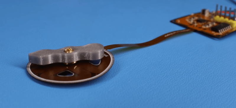
The motor and controller consist of a single flexible PCB, to reduce the layer spacing and increase the coils’ magnetic field strength. However, this created other problems, since the motor shaft didn’t have a solid mounting point, and the PCB flexed as the stator coils were energized. Soldering the controller was also a problem, as the through-hole headers ripped out easily and the PCB bulged while reflowing on a hot plate, in one case even popping off components. [Carl] eventually mounted one of the PCB motors inside a 3D printed frame to rigidly constrain all the motor components, but it still suffered from missed steps. Any suggestions for fixing the problem? Drop them in the comments below.
Like his other PCB motors, the torque is very low, but should be suitable for gauges or clocks. A PCB clock with an integrated motor would be pretty cool to have on the workshop wall.
The TMC2300 stepper driver [Carl] used belongs to the same family of drivers that enable silent stepping for 3D printers. We’ve covered a few of [Carl]’s PCB actuator adventures, from his original design to linear actuators and a flexible POV display.


The B-field over each of the coils cannot ever be uniform enough to step as finely as he wants….
Not even with a weird tapered geometry?
Don’t think stepper, think servo. (not RC servo, the other type).
What is needed is some sort of position feedback to close the loop.
The simplest system to start with is probably a set of Gray-coded tracks on the PCB and wiper contacts. But for long-term reliability without wear something capacitive like is used on digital calipers might be the answer.
I have a workshop full of CNC machine tools that commutate 3-phase motors in software and run the position loop in software. It’s 100% workable.
Actually….. It is probably possible to run the existing motor closed-loop using a camera and OpenCV to provide the position feedback.
Ever hear of an encoder?
Andy retrofited handful of machines to CNC with STMBL AC servo drives he assembled and programmed himself, so probably yes
Yes, I suggested a couple of ways to incorporate an encoder in my first message. But then thought of a way to close the loop without waiting for new PCBs to arrive.
The point of stepper motors is that feedback is not required for position if torque is no exceeded for a given size motor.
I think he is asking a lot for positioning from 4 fields that are oddly shaped. open up a 1.9deg stepper and notice how many fields are seriesed to get fin position, at full steps they move 1.9 deg, there are 200 n/s poles(thru steel)
> The point of stepper motors is that feedback is not required for position if torque is no exceeded
> for a given size motor.
Yes, that is the point of steppers. But the point of these motors seems to be to make a motor out of PCBs.
I was suggesting that a different mode of motor control might be worth investigating.
There really isn’t a lot of difference between a stepper and a brushless motor. There is even less difference between a high pole-count brushless motor and a 3-phase stepper. To the extent that you can run a brushless motor like a stepper (and often do for initial homing of servo motors with incremental encoders but no Hall sensors) or run a stepper as a 2-phase brushless servo motor (as they do with the “closed loop steppers” from Leadshine and others)
+1 More poles would give higher resolution, less chance of skipping
Regular steppers do have permanent magnets. Just turn them by hand, and feel the “detent” as the teeth on the rotor attract the teeth on the stator.
That’s just the residual magnetism. The core piece is ferromagnetic, and eventually picks up the magnetic orientation of the field, but if you force it around while the coils are powered, it will re-magnetize in a different orientation.
Not the modern ones (as in, made this century) they have a permanent magnet rotor.
Traditionally a magent with N-S oriented along the motor shaft axis, and then interdentated toothed pole pieces wrapped round the magnetic core. More recently I think that they are using simple toothed rotors with the poles magnetised in.
You might be thinking of “variable reluctance” motors?
What would happen if he made a sandwich ? pcb-rotor-pcb or rotor-pcb-pcb-pcb-… ? That would make stronger magnetic filed or not ?
Thanks for sharing the review.
Je pense qu’il suffirait de positionner un deuxième étage de solénoïdes décalé de 45 degrés au dessus du rotor.
If flexibility is his only problem why not solder the flex pcb down to a rigid pcb at specific points, such as just outside the coil. Then he gets the rigidity and the low layer heights or whatever from the flex. He could even make it a skeleton type rigid frame if the rigid pcb would interfere with the b field
I’ve once driven 5V steppers from 3.5″ HD floppy drives and found that A4988 drivers worked better than drv8825s. You’ll need to carefully set the drive current and the stepping should be much smoother. 1/4 microstepping should be quite stable whereas 16x can be less acurate/stable. I haven’t tried trinamic 2300. It’s important that the drive current goes low enough so it doesn’t overshoot but high enough that the inertia of the rotor can be overcome. The drive voltage can also have an impact how accurate the stepper driver works.
or use small Switec stepper motors that can be microstepped if needed. These are used in car vehicle instrument clusters.
https://embeddedtronicsblog.wordpress.com/2020/12/12/tiny-stepper-motors/
Jim, how do these Switec motors find home? I don’t see position feedback in the link you sent. Are they driving to a mechanical stop and sensing current overload?
It acts as a regular stepper motor. In the video I have it spin 5 revolutions and reverse. Then spin 1 revolution at a slower speed. Repeat.
No closed loop position feedback. And no mechanism stop. It originally had a internal mechanical stop but I removed it do the motor can spin continuously.
Curtis,
To move the motor, I’m using a arduino Uno running grbl and a Trinamic TMC2225 stepper driver. grbl is a cnc control program. Simple gcode program to move forward and reverse. Speed and amount of rotation can be set.
Your components are popping off the board because you are heating them too quickly. Solder paste and component manufacturers publish a thermal profile that you should follow when reflow soldering boards. The initial soak cycle is important to reduce thermal shock and stop the flux in the paste from boiling. You should also check that you aren’t getting water in your paste from humidity in the air during storage.
“The NEMA stepper motors most of us know are synchronous stepper motors, while [Carl]’s design is a permanent magnet design.”
A permanent magnet motor is still a synchronous motor. Asynchronous motor (aka induction motor) is running at delayed speed because it works like a transfomer. The induced current in the aluminium rotor bars (squirrel cage) is laging behind by half a period.
Modern steppers are hybrid as they have both a reluctance rotor and permanent magnets on the rotor to make them run smoother.