
For as many of them as we’ve seen, we still love a good persistence of vision display project. There’s something fascinating about the combination of movement and light creating the illusion of solid surfaces, and there’s always fun to be had in electromechanical aspects of a POV build. This high-resolution spherical POV display pushes all those buttons, and more.
Called “Flicker” for obvious reasons by its creator [Dan Foisy], this POV display started with a pretty clear set of goals in terms of resolution and image quality, plus the need to support animated images, all in a spherical form factor. These goals dictated the final form of the display — a PCB disc spinning vertically. The shaft has the usual slip rings for power distribution and encoders for position feedback. The PCB, though, is where the interesting stuff is.
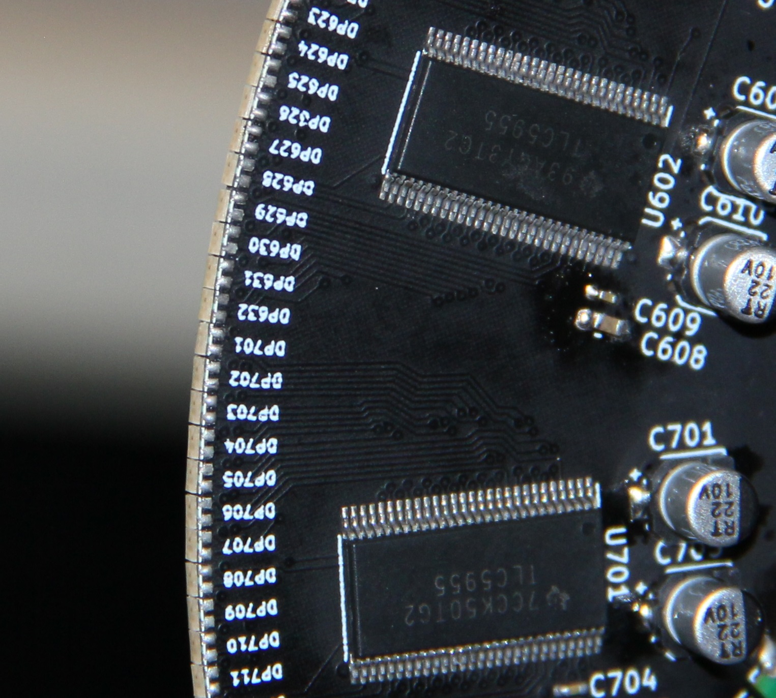 [Dan] chose to use an FPGA to slice and dice the images, which are fed from a Raspberry Pi’s HDMI port, to the LED drivers. And the LEDs themselves are pretty slick — he found parts with 1.6 mm lead spacing, making them a perfect fit for mounting on the rim of the PCB rather than on either side. A KiCAD script automated the process of laying out the 256 LEDs and their supporting components as evenly as possible, to avoid imbalance issues.
The video below shows Flicker in action — there are a few problem pixels, but on the whole, the display is pretty stunning. We’ve seen a few other spherical POV displays before, but none that look as good as this one does.


That’s pretty spiffy!
Awesome work !
Very Cool!
I can recommend some simplification in the motor / slip ring / timing mechanism for version 2 :)
You can now buy brushless gimbal motors designed for drone camera gimbals which include both multi-wire slip rings and high resolution encoders all in one package effectively.
Here’s one with a spot for a 12-wire 12.5mm slip ring and a AS5048A 14-bit encoder is available for it.
https://shop.iflight-rc.com/index.php?route=product/product&path=34_44&product_id=279
I don’t think the motor you’ve linked would be fast enough, the specs on the page says RPM:456~504 that’s well within human visual threshold. It would need to spin at a couple of thousand RPM to support POV.
The linked write-up says that this one is “only” spinning at 15Hz, or 900RPM…
It also says that he’s already using a slip ring rated for 600RPM.
That’s pretty cool. They had trouble getting some of the LEDs to connect to the pads on the PCB becaue JLPCB cut the board a little bigger than it should have been. I’m curious why they didn’t try to sand it down a little bit to get it to size.
Tangentially, I have a habbit of sanding board down when I get them if they have rough sides–vcut, etc. I just prefer the feel of that smooth routed type of edge. 400-600 grit works great–cuts fast and gives a smooth feeling edge. Clearly, if you’re doing a lot of boards or large boards, be careful with ventilation. You don’t want to breath in any of the epoxy or glass fiber dust.
My guess is the pad to edge distance was too small according to the fabrication requirements so the manufacturer just increased the outline so it would meet their requirements (perhaps this was a better choice than insetting the pads instead). I think they do this so that their router bits aren’t dulled by copper that goes right up to the edge of boards. The exception is castellated pads but for that most fabs have an extra charge.
Yes, I would expect the board manufacturer assumed based on manufacturing rules that it was safer to leave space between pads and the cut edge so that none of the pads are compromised by the edge routing. Unfortunately that was the wrong assumption.
But it has nothing to do with the cutting bits. Copper is very soft (even hardened it scratches easily with mild steel), and glass fibers are much harder on the bits.
He did sand it down, but it was imperfect.
He could have a custom HDMI cable made on flex PCB to eliminate that awkward cable he’s using now.
He could have used a Compute Module and eliminate the useless connectors.
If you offset the LEDs on the opposing side, you can use a technique similar to “micro stepping” to get the perception of much higher resolution than you already have. You essentially fill in the gaps between LEDs that you currently have, and use the persistence of vision to also create combination pixels. You’ll end up with 3x+ linear resolution (you could use the same concept in the tangential direction too for increased resolution if your LED driver can handle the refresh rate) . You would lose out on the full frame rate because you need multiple revolutions to paint a single frame, but you could offset that by simply spinning faster.
Good idea, more Sub-Pixel anti-aliasing technique.
This is a amazing job here, very pro, even if not a commercial product! Awesome and very well written down (not a lengthy video)
We need more stuff like this here on HaD!
This is covered in the article.
This sounds like how interlacing was done on CRT TVs to get higher resolution at faster refresh rates.
Im impressed.
He seems to have tried that, and has a few issues (board alignment with rotation and multiple monochromatic LEDs) that made it worse than just making it symmetrical.
Would be an awesome portal display with some head tracking
Excellent build! engineered to look fantastic :)
What would be really neat is having LED’s on one side and colour sensor’s on the other side, Build two of these with RF link.
They would act like light portals. teleporting the surrounding world from one to the other