When working around mains voltages, it can be useful to know whether a given circuit is live or not. While this can be done by direct connection with a multimeter, non-contact methods are available too. A great example is this simple wireless AC current detector from [NEW PEW].
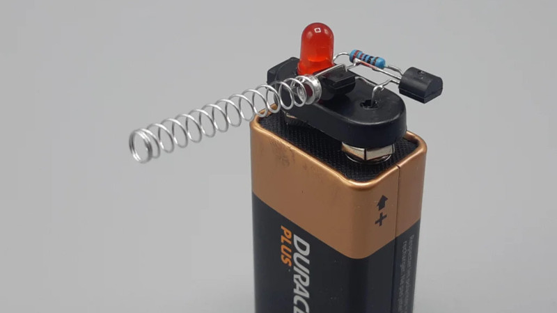
The circuit is a simple one, and a classic. The spring from a ballpoint pen is soldered to the base of a BC547 transistor, and when held close enough to a conductor carrying AC power, a current is induced in the spring which is sufficient to turn the transistor on. The transistor then switches on a second BC547, which lights an LED. The whole circuit is built on top of a battery clip so it can be run straight from the top of a standard 9 volt battery.
It’s a circuit you’ll find all over the place, even built into many modern multimeters. It can be particularly useful to help avoid drilling through mains wires embedded in the walls of your home. Of course, if you’d like even more information about what’s lurking within your walls, consider this capacitive imaging hack. Video after the break.


Does this detect if a conductor within the cable is hot, or only when there’s current flowing to a running load supplied by the cable?
It’s detecting changes in the ambient electric field. It’s basically a baseband radio receiver, using the battery as earth and the spring as the aerial.
yes, it detects Live not Load
That’s not a current detector. It’s a voltage detector.
And Instructables desperately needs to raise the bar.
So does HaD, I’m sorry to say.
I think Instructables allows the user to enter the title, so its really on the author.
still it was a nice beginners project.
I concur, the adept would not use a spring, but a paperclip bent into the Eye of Horus.
Only if he had enough sulfur powder in shoes. Even then, a pin is better.
You’re wrong as well – it’s not a voltage detector. It’s an EMF detector.
If anything, it’s actually closer to current rather than voltage detector as the bipolar transistor used here is “sensing” the current going into its base.
If you need to rant in your comment at least make sure you’re correct.
More on topic, the device is simple but serves its purpose. It’s also nicely done. This is one of the hacks that it’s good to have in the back of your head when you find yourself in a situation where you need to detect wires in the wall before drilling or if you want to detect if a small RF signal is present in the circuit or not.
I’ve built a similar one years ago but used a speaker instead of an LED.
I personally like this project. I think the best way to learn is to find a way to do something with as few parts as possible and this guys videos really help with that. I watch them sometimes just to learn to be better at dead bug soldering.
I think its a requirement in HAD comments for someone to shit all over any project in a narcissistic attempt to show their mental superiority only to be proven wrong moments later. That said I think we have all done this at some point and its a good way to learn to be humble :)
Instead of buying a 9 volt battery clip, disassemble a dead 9 volt battery and use its top.
Instead of using a fresh 9V battery, use an old one out of a smoke detector, there’s probably still 5V in there, enough to light the LED.
I leave some of mine in a year rather than the 6 months recommended and there’s still over 9v showing on most of them, 8.5 at the worst.
Energisers are just sprung fitted together with a rubber pad in the bottom, so crack those open and you can get the PP3 connector off the top without having to cut or pry any connections off. Also you’ll notice the interior cells are pretty much AAAA sized if you’ve got any gizmos that need those. Might need a small washer or nut jammed in one end if they’re a mm or two too short for the spring in the device to cope with though.
When a cell is depleted, the no-load voltage doesn’t drop much. It’s the internal resistance that rises, and battery testers have a ~100 ohms load.
That would be piddling for a D cell but 9Vs are only a few mAh capacity and devices designed to use them only pull a few mA and they are only expected to supply a few mA. Pull much and they go flat quick.. https://www.powerstream.com/9V-Alkaline-tests.htm
I have a pedantic pet peeve where I wish folks would be a little more precise when they talk about electrical circuits around the house. I see time and again advertisements that talk about this or that appliance that uses 120v current etc. It could be 120 volts, 120 v power, etc., but not 120v current.
This is one of those. To be strictly accurate, there is capacitively coupled power into the base of the transistor, but from a general sense when you hold the detector close to a “live” circuit, you are sensing if there is voltage on the circuit, not current. If there is current flow or not, it wouldn’t change the detector results.
Instead of “a little more precise” I’d settle for “not dead wrong”.
And I’ll see your pedantry and raise you one: The abbreviation for volt is “V”, not “v”, and there must be a space between the value and the unit, e.g. “120 V”
Instead of “a little more precise” I’d prefer “a little more accurate”.
After all, we are engineers.
So “Simple Alternating Current Current Detector Built On A 9 Volt” does not succinctly capture the essence of the project? I tend to agree. This is getting to be like Slashdot.
You, Sir, are two current with your reply!
I on the other hand, am uncertain, and my uncertainty is just the tip of the Heisenburg.
” The abbreviation for volt is “V”, not “v”, and there must be a space between the value and the unit, e.g. “120 V””
Yes. Absolutely correct. Thanks!!
“I see time and again advertisements that talk about this or that appliance that uses 120v current etc. It could be 120 volts, 120 v power, etc., but not 120v current.”
I’m not sure what part of the article or video you are replying to, but mentioning current in regards to voltage isn’t absurd. Think about the term 120VAC – it refers to 120 volts, alternating current. If I missed the mark on what you are trying to say, my apologies.
Watt was that about 120 V Power, …sorry, couldn’t resist….:-)
I have no problem with the term VAC. It’s not what I said and is not the issue with the project description.
i might be rusty with my ohm’s law.
I would think alternating voltage and alternating current.
I would imagine there is “current” even if the circuit is not complete. (without load)…
maybe I am wrong?
Don’t be too pedantic or Stephen Hawking will get you…
https://www.youtube.com/watch?v=VPOa72dsrGw
Oh I don’t mind it, it’s a quick wat of knowing if I should continue with the article or not
Anyone ever find one of these for detecting energized DC wires, not under load?
A metal detector, because every stray length of wire is a DC wire not under load.
Something very similar was in an old Radio Shack 50-in-1 electronic kit. I need to put it together to find a dead spot in my Christmas light line.
Good idea. I have the same problem, but in a 4 channel LED light string. I have to find out, if the controller can switch on one channel for some longer time.
I would like to buy this Guy a small vice so that he doesn’t drill his fingers in the future. But… all joking aside… BRAVO! Nicely done!
That would be “vise”…
Electroboom did it a year ago…https://youtu.be/D2ekBjrHzYo
Is the BC547 the new goto transistor for these builds?
It’s unspecial, generic NPN small signal types could replace it, pick yer poison.
Yes, after the BC107 and later the BC238.
Ugh. Both an incomplete Instructable AND a YouTube Video to explain something that would take a small hand-drawn schematic to explain in ten seconds. Welcome to the 21st century on planet Earth brainwashed by Social Media.
Then there are the design problems…
Circuit Description: The emitter of an NPN Darlington pair passes through a 220 Ohm current limit resistor in series with a red LED who’s cathode is connected to the negative terminal of a 9V battery. The collector of the Darlington pair goes to the positive terminal of the 9V battery. The base of the Darlington pair connects to the antenna probe.
Problem-1: The designer specified using a venerable BC547 NPN epitaxial transistor, but the TYPE of BC547 transistor was not specified. The BC547 transistor has a current gain (hfe) specification that ranges from 110 through 800 in three tiers, A, B, and C. This is from a current ON Semiconductor BC547 datasheet:
BC547A; Vce = 5 V, Ic = 2 mA; hfe = 110 min. 180 typ. 220 max.
BC547B; Vce = 5 V, Ic = 2 mA; hfe = 200 min. 290 typ. 450 max.
BC547C; Vce = 5 V, Ic = 2 mA; hfe = 420 min. 520 typ. 800 max.
The ON Semiconductor datasheet can be found here:
https://www.onsemi.com/products/discretes-drivers/general-purpose-and-low-vcesat-transistors/bc547
The three BC547 variants are still readily available and they typically all cost the same, about $0.22 USD each in unit quantity. Therefore, the obvious choice would be to specify the BC547C with its higher current gain. Be sure to buy BC547C transistors made by trusted manufacturers and reputable distributors. These transistors are one of the most counterfeited in the World.
Problem-2: The designer did not specify the LED part number. The LED selection is critical to battery life. Obviously you want to specify an LED that provides high brightness with a very low forward current. Such specialty LEDs exist.
The fix: The BC547C has a minimum hfe of 420 which is still pretty high, especially when we are using two transistors in a Darlington pair. A high brightness red LED is selected that is usable with a Vf of 2mA. Now we can estimate the series current limit resistor value to be used.
Let’s assume the Darlington pair is saturated in operation (or close to it), the Vce drop and Ib contribution are negligible, the LED If is 2mA, the LED Vf is 2.3V, and Vbat is 9.0V. The value of the series current limit resistor is approximately:
(Vbat – Vf) / If = (9.0V – 2.3V) / 2E-2A = 3,350 Ohms
Let’s use a standard 3.3K Ohm resistor. Now we estimate how much longer the battery will last with the new resistor value:
100 * (3,300 / 220) = 1,650% longer with the 3.3K Ohm resistor versus the originally specified 220 Ohm resistor.
This is a back of the envelope estimate since I have no data on what the actual antenna pick-up looks like in practice. Some experimentation to optimize the limit resistor value is called for. Regardless, given the careful part selections I have introduced I believe the series limit resistor value will still end up being much higher than the original 220 Ohms.
Problem 1: if your design is dependent on the Hf of the transistor, you’re usually doing it wrong. This design will work fine with any of them. Just about any random red LED will light up visibly with a few hundred microamps of current, and the Darlington pair will have a current gain of >12,000 in the worst case.
It is not necessary for the application to run the transistors to saturation, and using a more sensitive part could actually make the circuit so that it picks up static charges and blinks the LED randomly just from holding it in your hand, which would defeat its purpose.
Problem 2: the LED current isn’t critical for battery life because the LED will not be on constantly. This application is very low duty cycle and the shelf life of the battery is the limiting factor. Since we’re most likely operating in linear mode rather than saturating the Darlington pair, the resistor is just there to limit the maximum possible current.
Understand the application and the requirements before you criticize the implementation, and don’t fix what ain’t broken.
@Dude said: “Problem 1: if your design is dependent on the Hf[e] of the transistor, you’re usually doing it wrong.”
My approach uses the minimum specified hfe for the BC547C from the datasheet. Therefore it is hfe independent at a given temperature.
“This design will work fine with any of them [transistors].”
You are missing the point. The original design wastes far too much power. Selecting the transistors, LED, and limit resistor properly fixes that.
“Just about any random red LED will light up visibly with a few hundred microamps of current…”
Nah, “a few hundred microamps of current” may light even a low current high brightness LED, but that doesn’t make the end product truly useful in all environments such as well lit rooms or even direct sunlight.
“…and the Darlington pair will have a current gain of >12,000 in the worst case.”
>12,000? That means the current gain of an individual transistor would be sqrt(12,000) = 109.5, which is pretty low. In fact the minimum specified hfe of the BC547A is 110, which makes my point that the original design is under specified. And by the way, you are way off with 12,000. In my example with two BC547C transistors the total current gain is at least 420^2 = 176,400, typically 520^2 = 270,400, and as high as 800^2 = 640,000.
“It is not necessary for the application to run the transistors to saturation…”
What you say here is true, but you are missing the point entirely. I assumed the transistors were at or near saturation for the purposes of properly calculating the series current limit resistor value.
“…and using a more sensitive part could actually make the circuit so that it picks up static charges and blinks the LED randomly just from holding it in your hand, which would defeat its purpose.”
In my post I clearly stated that some experimentation would be required to arrive at a final design. It may be true that the higher gain circuit would be overloaded with the relatively large spring voltage probe used in the original design, which is good, make the probe much smaller. In-fact, I would go even further and add negative feedback which would not only allow for gain adjustment, it can also make the circuit unconditionally stable. As for picking up static charges or coupling from a hand, ideally the circuit would be entirely shielded except for the probe.
“Problem 2: the LED current isn’t critical for battery life because the LED will not be on constantly. This application is very low duty cycle and the shelf life of the battery is the limiting factor…”
I entirely disagree. Anytime a circuit unnecessarily draws current from a stand alone battery, it’s a critical problem. Ideally the circuit would run in the linear region, even then the LED will be on for a significant amount of time. However, it’s more likely the circuit run in or near saturation where the LED is on all the time.
“…Since we’re most likely operating in linear mode rather than saturating the Darlington pair, the resistor is just there to limit the maximum possible current.”
Exactly, and I argue that in the original design the 220 Ohm resistor used is far too small, so it wastes power. Notice that when I calculated a new value for the limit resistor I stated that I assumed that the circuit was at or near saturation, as it should be.
“Understand the application and the requirements before you criticize the implementation, and don’t fix what ain’t broken.”
That’s sentence is just plain wrong. I demonstrated that I fully understood the original design, and then went on to suggest real improvements. As far as the “…don’t fix what ain’t broken” statement goes; just because a design “works” doesn’t make it a “good” design. I think the original designer should have spent more time designing and less time posting Instructables and making YouTube videos.
>You are missing the point. The original design wastes far too much power. Selecting the transistors, LED, and limit resistor properly fixes that.
That was never an issue to begin with, and you just made up your own criteria to “fix” it accordingly.
>which makes my point that the original design is under specified
No it doesn’t. The lowest specified Hfe for any of the variants gives a current gain of at least 12,000 which means the LED lights up visibly when it’s picking up some few dozen nanoamperes, which is good enough. Any of the BC547 transistors you could pick would work well enough.
> I assumed the transistors were at or near saturation for the purposes of properly calculating the series current limit resistor value.
There is no “proper” resistor value here because the voltage at saturation is constantly changing with the battery SoC. If anything, a low value should be selected to keep the LED shining to as low a voltage as possible, because otherwise the circuit stops working before the battery is empty. You didn’t take that into account at all.
>Anytime a circuit unnecessarily draws current from a stand alone battery, it’s a critical problem.
How much current the LED draws for the short time of actual duty is not a critical issue. A 9 Volt battery has about 500 mA of capacity typically, and even if the whole circuit drew 25 milliamps, you would have 72,000 seconds of operation. You will not exhaust the battery by using it, it will go empty by sitting in your drawer or toolbox, so there was no sense in trying to optimize the current consumption.
>I assumed that the circuit was at or near saturation, as it should be.
There is no logic or reason behind that assertion.
> I demonstrated that I fully understood the original design, and then went on to suggest real improvements.
No, you didn’t. All you did was waste time in an attempt to look smart.
Besides, the AC waveform results in a 50% duty cycle, so the effective number of milliamp-hours you can expect from the battery is doubled. If one positive measurement takes one second, you can expect 144,000 indications even when the LED is running at 25 mA.
There is no reasonable use case where this device would be used enough times to warrant optimizing the current consumption in any ways.
> As for picking up static charges or coupling from a hand, ideally the circuit would be entirely shielded except for the probe.
The circuit works because there is a leakage path through the battery’s metal casing, via the user’s hand and body, to the earth ground. If you put it in an insulated box with only the probe tip sticking out, it stops working.
Again, just goes to show that you don’t even understand the circuit.
Besides, you forgot in your analysis that a 9 Volt battery is never 9 Volts, but goes from 9.6 Volts down to 4.8 Volts minimum before it stops giving out current. Some alkalines have weird “plateaus” even at the empty voltage where some other chemical reaction kicks in and keeps sustaining the current.
Secondly, you forgot that the LED forward voltage depends on its forward current, especially so when you’re using them at low currents. A LED with a nominal current draw of 20 mA at 2.3 Volts can still light up visibly with 1 mA at 1.8 Volts, because it’s a diode. It’s non-linear. There is no simple way to calculate your battery life unless you’re using a constant current regulator… so basically none of your math has any relevance.
@Dude said: “Besides, you forgot in your analysis that a 9 Volt battery is never 9 Volts, but goes from 9.6 Volts down to 4.8 Volts minimum before it stops giving out current. Some alkalines have weird “plateaus” even at the empty voltage where some other chemical reaction kicks in and keeps sustaining the current.”
Again, you are missing the point. I assumed the battery voltage was at 9.0V specifically to calculate the value of the series current limit resistor. In this case I don’t care if the battery voltage is lower. And yes assuming 9.6V for a fresh battery rather than 9.0V would have been better, but it would not make a big difference (e.g. maybe a 3.7K resistor versus 3.3K).
“Secondly, you forgot that the LED forward voltage depends on its forward current, especially so when you’re using them at low currents. A LED with a nominal current draw of 20 mA at 2.3 Volts can still light up visibly with 1 mA at 1.8 Volts, because it’s a diode. It’s non-linear.”
Nope, I didn’t “forget” this. Notice how I assumed a red LED Vf value of 2.3V, normally it would be about 1.8V at a nominal If of 10mA or 20mA. But the goal is to run the LED at a much lower forward current, in this case 2mA. At 2mA the Vf would be higher, that’s why I assumed a Vf of 2.3V instead of 1.8V. If I “forgot” anything, it was not stating that assumption in my post.
Note: The Vf values of 1.8V and 2.3V are just informed guesses. In a real design I would ideally refer to the LED’s datasheet, use the datasheet of a similar “bubble-gum” red LED, or at least use Shockley’s diode equation.
Try again. You got it backward. LED Vf vs current looks a lot like the diode it is: Vf will be lower at lower current.
A modern red LED at 2.3 V is going to be pretty close to toast: that kind of Vf is relevant only for pulsed applications.
>I assumed the battery voltage was at 9.0V specifically to calculate the value of the series current limit resistor.
Which is not meaningful, because the voltage will drop anyways. A half-empty 9 Volt battery is more like 7.5 Volts and at 6 Volts you still have 10-20% capacity left. The resistor value you chose will be too large for the lower voltages.
You tried to optimize the circuit for a full battery, without realizing that you’re cutting the useful duty from the other end of the battery voltage range.
> At 2mA the Vf would be higher, that’s why I assumed a Vf of 2.3V
As the other guy said: wrong.
I picked up one of these that runs off a single AAA cell, has a light and a beeper. It’s also fully insulated with a tab that can poke into outlets. It even works on low voltage DC stuff like USB cables. Shows that my laptop is emitting a field from just about every bit of its exterior, except for *one little spot right there*.
Maximum range is pretty short, around 1/4″, so it can be used to identify which side of Romex has the hot wire.
I made one too, with sziklai pair instead of darlington pair. Another difference was that it was earth detector instead of live voltage detector. I used to have a UPS that shocked me frequently. I left my simple sziklai pair based circuit on top of it, and I noticed that whenever I bring my hand near to it, the LED brightened. The LED brightened more when I bring hand close AND I touched wall or didn’t wear foot wear. Instead of bringing hands near, a dry book, and many other seemingly insulating objects also made the LED glow.
I like when such a simple circuit spawns so many comments haha.
I’ve got a Fluke Voltalert, and wouldn’t trust my life on it. Nothing beats probing if you can!
Although I do agree to a point, there are times when a non contact voltage wand is a better option than a multimeter. E.g.; a light bulb fixture with two switches will read 0VAC across the terminals when both terminals are at line voltage.
Line voltage will appear on both terminals only if it’s wired incorrectly.
What do you mean?
I assume we’re talking about a ceiling socket or wires sticking out for two bulbs. In that case there would be two switches for two hot wires and one neutral, and possibly one earth ground wire.
The switches are on the hot side of the circuit, so when the circuit is powered off there is no voltage at the socket in the ceiling. You seem to suggest there would be one hot wire and two neutrals with switches on the neutral side, because only that way you can have just one hot wire to the socket.
If I remember correctly, the codes prohibits neutral side switching unless the same switch also disconnects the line voltage from the circuit, because otherwise you could be having a device with a short-to-chassis fault and you have to go all the way to the breakers to disconnect it. In a light fixture, the bulb socket threads are exposed to the user when they’re changing the bulbs, so changing the setup to switch the neutral side can create an electrocution hazard under normal conditions as well.
“codes prohibits neutral side switching” – but that does not change the fact, that it exists. Or special version of a two switch setup: Each of the two light switches changes over between L and N. If the bulb has both, it lights up, if it has 2*N or 2*L it does not. This setup is 2 times dangerous: The risk of electric shock, when you think it is switched off and the risk of arcing over between L and N in the switch.
But I have already encountered such a circuit.
“What do you mean? ”
I interpreted “a light bulb fixture with two switches” to mean a conventional three-way circuit: one fixture with two switches, either of which can turn on or off the light. If you wire this circuit incompetently you can get hot on both terminals, and it still appears to work correctly.
It seems you’re interpreting “a light bulb fixture with two switches ” as “a light bulb fixture with two separate switched light circuits (sharing that pair of terminals mentioned)”. Which, frankly, I’ve never seen in 40+ years of house wiring, and which probably violates code. Even fan-light combinations make the connections distinct. Industrial though, yes, this can happen, in which case the appliance is always clearly marked as having two separate sources.
Line voltage would appear on both wires to a single bulb socket also when there’s a fault in the wire, for example, someone drove a nail or a screw into the cable and a loosely connected junction box had the wire end burn up and disconnect instead of tripping the breakers.
The meter would read zero volts across live and neutral, while the voltage wand would light up to indicate that both wires are in fact live.
Then measure it against PE.
Wow, the comments can easily earn this article the “Pedantic Corection Award’s”.