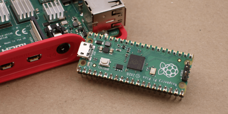
Raspberry Pi was synonymous with single-board Linux computers. No longer. The $4 Raspberry Pi Pico board is their attempt to break into the crowded microcontroller module market.
The microcontroller in question, the RP2040, is also Raspberry Pi’s first foray into custom silicon, and it’s got a dual-core Cortex M0+ with luxurious amounts of SRAM and some very interesting custom I/O peripheral hardware that will likely mean that you never have to bit-bang again. But a bare microcontroller is no fun without a dev board, and the Raspberry Pi Pico adds 2 MB of flash, USB connectivity, and nice power management.
As with the Raspberry Pi Linux machines, the emphasis is on getting you up and running quickly, and there is copious documentation: from “Getting Started” type guides for both the C/C++ and MicroPython SDKs with code examples, to serious datasheets for the Pico and the RP2040 itself, to hardware design notes and KiCAD breakout boards, and even the contents of the on-board Boot ROM. The Pico seems designed to make a friendly introduction to microcontrollers using MicroPython, but there’s enough guidance available for you to go as deep down the rabbit hole as you’d like.
Our quick take: the RP2040 is a very well thought-out microcontroller, with myriad nice design touches throughout, enough power to get most jobs done, and an innovative and very hacker-friendly software-defined hardware I/O peripheral. It’s backed by good documentation and many working examples, and at the end of the day it runs a pair of familiar ARM MO+ CPU cores. If this hits the shelves at the proposed $4 price, we can see it becoming the go-to board for many projects that don’t require wireless connectivity.
But you want more detail, right? Read on.
The Specs and the Luxuries
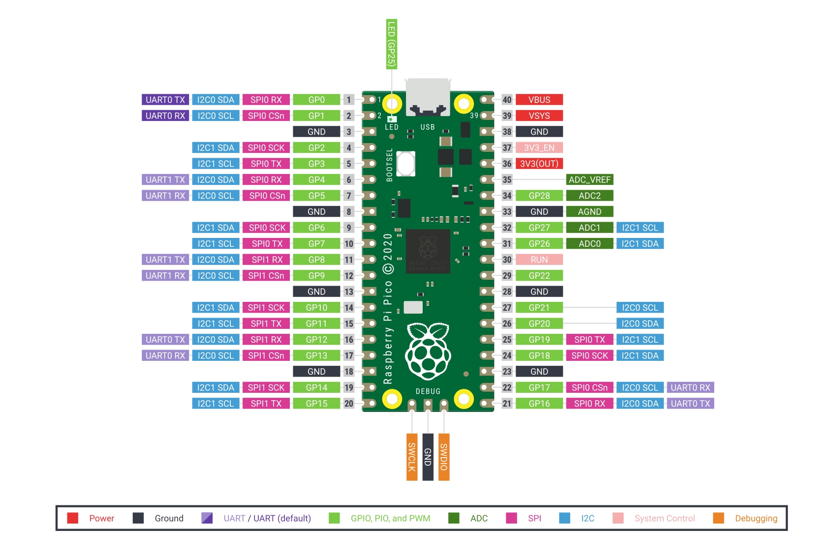
In many ways, the Pico is a well-appointed “normal” microcontroller board. It has 26 3.3 V GPIOs, a standard ARM Serial Wire Debug (SWD) port, USB host or device capabilities, two UARTs, two I2Cs, two SPIs, and 16 PWM channels in eight groups. (The PWM unit can also measure incoming PWM signals, both their frequency and duty cycle.) The Pico has a 12-bit ADC, although it’s connected to only four three pins, so you’ve got to be a little careful there. (Ed note: the RP2040 has four ADCs, but the fourth isn’t available on the Pico.)
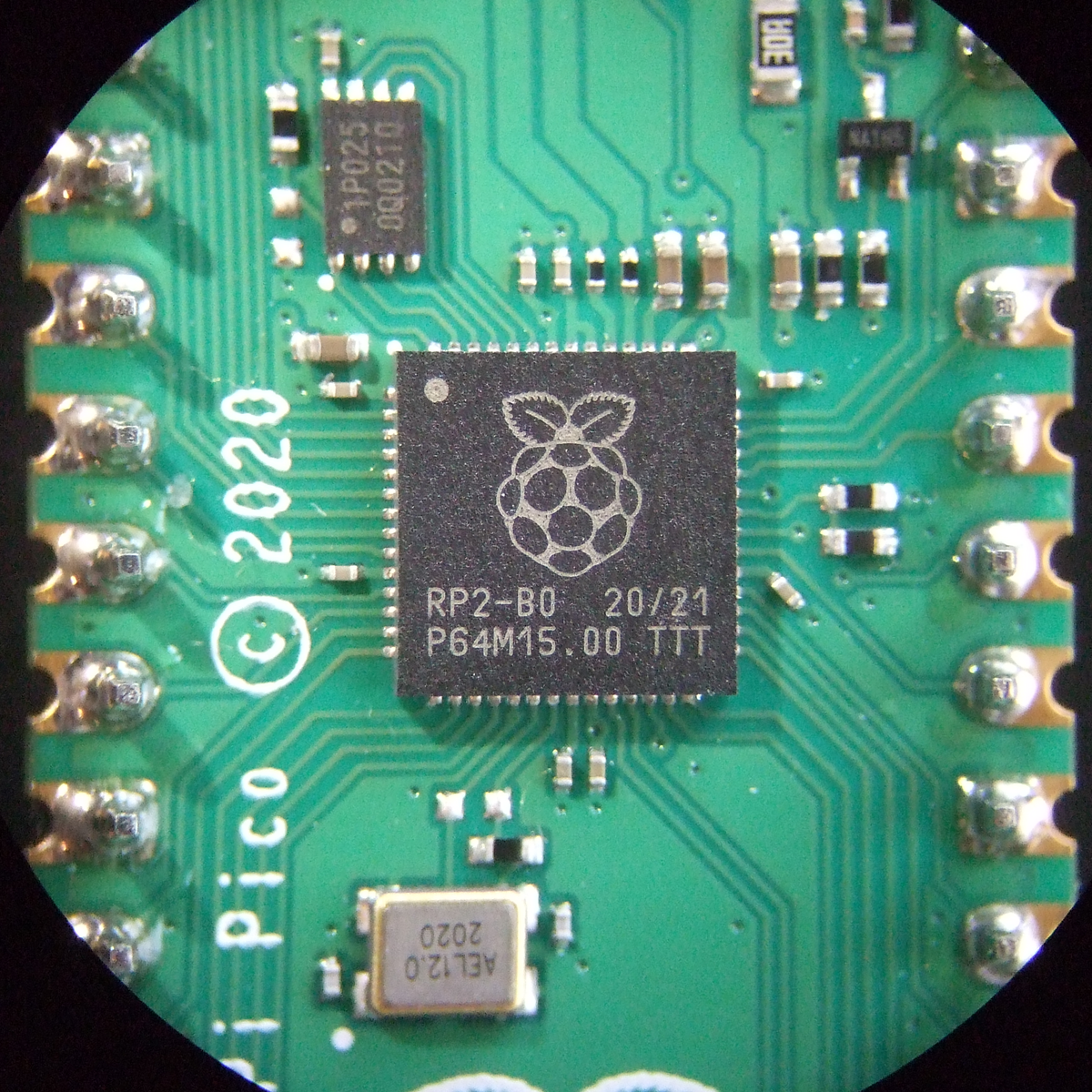
The twin ARM M0+ cores run off of PLLs, and are specced up to 133 MHz, which is pretty fast. There are separate clock dividers for nearly every peripheral, and they can be turned on and off individually for power savings, as with most other ARM microcontrollers. It runs full-out at around 100 mA @ 5 V, and has full-memory-retention sleep modes under 1 mA.
As the ESP8266 and ESP32 modules do, it uses external flash ROM to store programs, and can run code directly from the flash as if it were internal memory. The Pico board comes with a decent 2 MB QSPI flash chip, but if you’re handy with a soldering iron, you can fit up to 16 MB. It has 264 kB of SRAM, which is certainly comfy. The RAM is divided up internally into four striped 64 kB banks for fast parallel access, but they’re also accessible singly if you’d like. Two additional 4 kB banks are non-striped and suggest using themselves as per-core stack memory, but nothing forces you to use them that way either.
There are numerous minor hardware-level conveniences. All of the configuration registers are 32 bits wide, and so you might not want to have to specify all of them, or maybe you want to avoid the read-modify-write dance. Like many of the STM32 chips, there is a special memory map that lets you set, clear, or XOR any bit in any of the config registers in a single atomic command. There are also 30 GPIOs, so they all fit inside a single 32-bit register — none of this Port B, Pin 7 stuff. This also means that you can read or write them all at once, while setting individual pins is easy through the above atomic access.
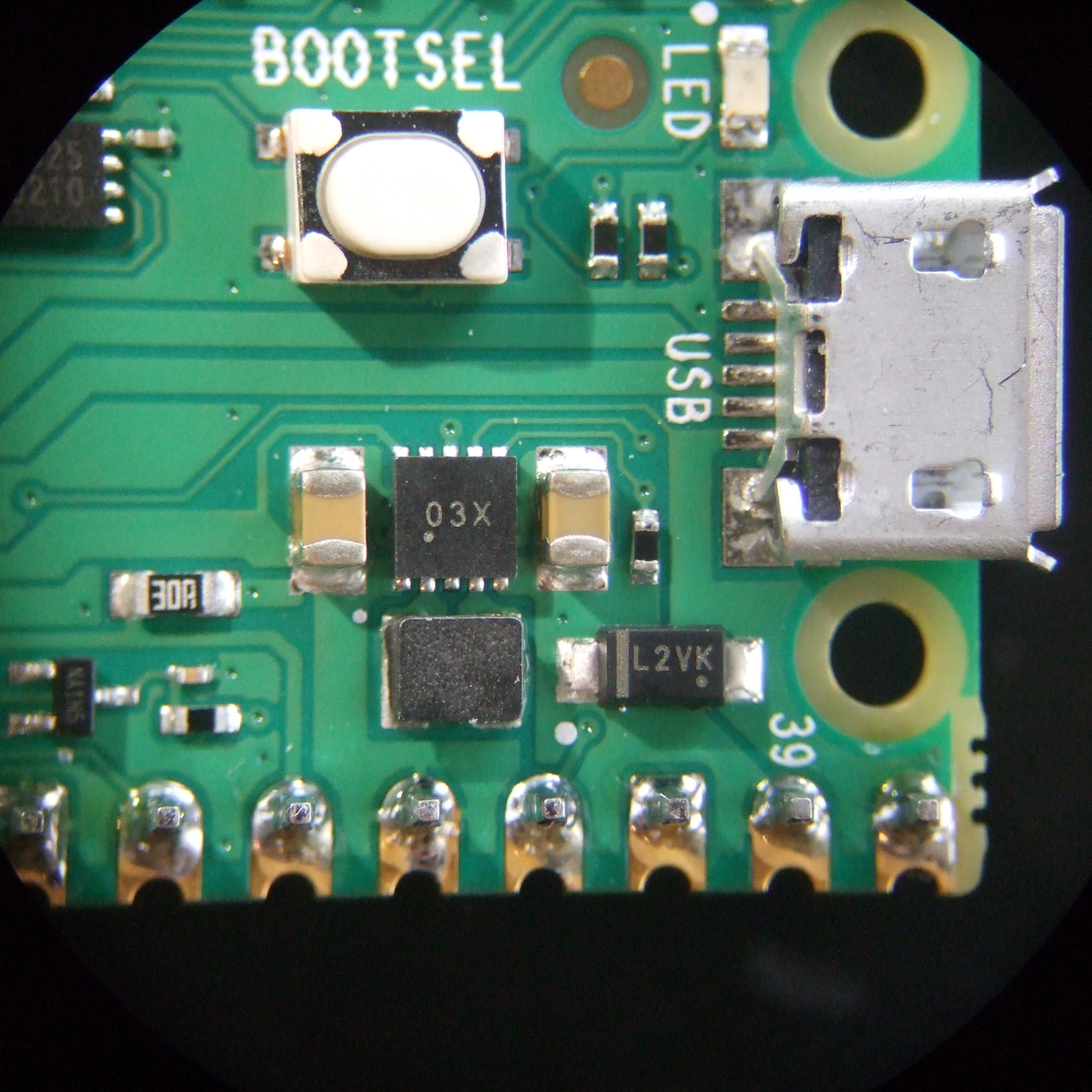 An internal mask ROM contains the UF2 bootloader, which means that you can always get the chip back under control. When you plug the Pico in holding down the BOOTSEL button, it shows up as a USB mass storage device, and you can just copy your code across, with no programmer, and Raspberry even provides an all-zeros file that you can copy across to completely clean-slate the machine. If you copy the Pico’s MicroPython binary across, however, you’ll never need the bootloader again. The mask ROM also contains some fast routines that support integer and floating point math, and all of the contents are open source as mentioned above.
The power regulation onboard is a boost-buck configuration that takes an input from 1.8 V to 5 V. This is a good range for lithium batteries, for instance, which can be a hassle because they run both above and below the IC’s 3.3 V, so it’s nice to have a boost-buck regulator to squeeze out the last few milliamp-hours. Or you could run your project on two AAs. That’s nice.
So the Pico/RP2040 is a competent modern dev board with some thoughtful touches. But it gets better.
The PIO: Never Bitbang Again
The real standout peripheral on the RP2040 and the Pico is the Programmable I/O (PIO) hardware, which allows you to define your own digital communication peripheral. There are two of these PIO units, and each one has four programmable state machines that run sequential programs written in a special PIO assembly language. Each of the state machines has its own clock divider, register memory, IRQ flags, DMA interface, and GPIO mapping. These allow essentially arbitrary cycle-accurate I/O, doing the heavy lifting so that the CPU doesn’t have to.
 If you want to program another UART, for instance, it’s trivial. But so is Manchester-encoded UART, or a grey code encoder/decoder, or even fancier tricks. One of the example applications is a DPI video example, with one state machine handling the scanline timing and pixel clock, while another pushes out the pixel data and run-length encodes it. These are the sort of simple-but-fast duties that can bog down a CPU, leading to timing glitches, so dedicated hardware is the right solution.
The PIOs are meant to have a lot of the flexibility of a CPLD or FPGA, but be easier to program. Each state machine can only take a “program” that is 32 instructions long, but the “pioasm” language is very dense. For instance, the command to set pin states also has an argument that says how long to wait after the pins are set, and additional “side-set” pins can be twiddled in the same instruction. So with one instruction you can raise a clock line, set up your data, and hold this state for a defined time. A basic SPI master TX implementation is two lines.
Or take the example of the WS2812 LED protocol. To send a logical 1, you hold the self-clocked data line high for a long period and low for a short period. To send a logical 0, the data line is held high for a short period and low for a long one. Creating the routines to do this with reasonable speed in the CPU, without glitches, required a non-trivial shedding of hacker tears. With the PIO peripheral, writing a routine to shift out these bits with absolute cycle accuracy is simple, and once that’s done your code can simply write RGB values to the PIO and the rest is taken care of.
To run PIO code from C, the assembler is called at compile time, the program is turned into machine language and stored as a matrix in a header file, and then this can be written to the PIO device from within main() to initialize it. In Python, it’s even easier — the @asm_pio decorator turns a function into PIO code. You just have to write the “Python” function using the nine PIO assembly instructions and then hook it up to GPIO pins. After that, you can call it from your code as if it were a normal peripheral.
Having played around with it only a little bit, the PIO is the coolest feature of the Pico/RP2040. It’s just a little bit of cycle-correct programmable logic, but most of the time, that’s all you need. And if you don’t feel like learning a new assembly language — although it’s only nine instructions — there are a heaping handful of examples already, and surely folks will develop more once the boards hit the streets.
IDEs and SDKs: C and MicroPython
The Raspberry Pi single-board computers (SBCs), when combined with their documentation and examples, usually manage a nice blend of being simple enough for the newbie while at the same time not hiding too much. The result is that, rather than having the underlying system’s Linuxiness abstracted away, you get introduced to it in a friendly way. That seems to be what the Raspberries are aiming at with the Pico — an introduction to microcontrollers that’s made friendly through documentation and MicroPython’s ease of use, but that’s also not pulling any punches when you turn to look at the C/C++ code.
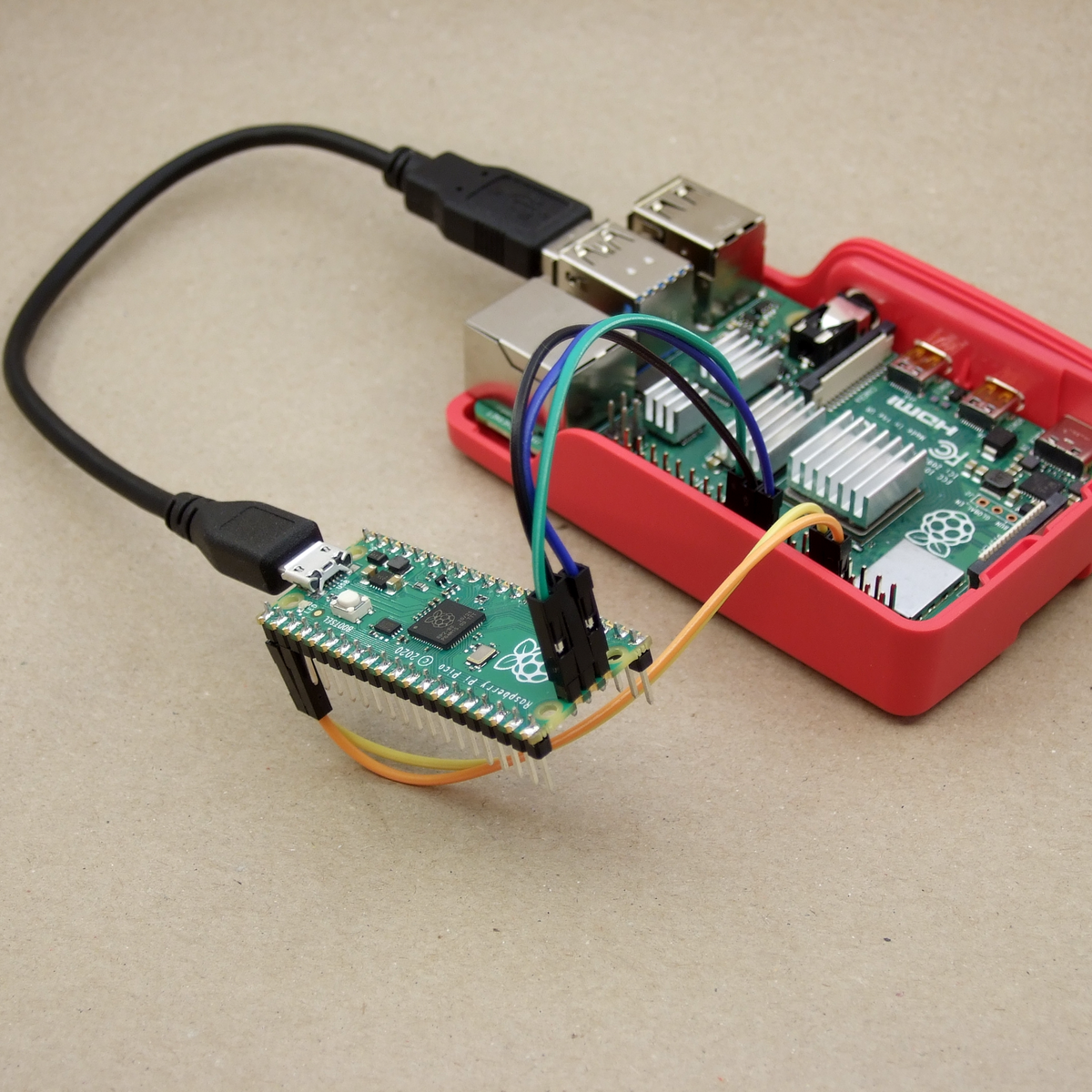
And having a Raspberry Pi SBC on hand makes a lot of the most hardcore microcontrollering simpler. For instance, if you want to do debugging on-chip, you’ll need to connect over the SWD interface, and for that you usually need a programmer. But of course, you can also bit-bang a SWD controller with the GPIOs of a Raspberry Pi SBC, but you’ll have to configure OpenOCD just right to do so.
If that all sounded like gibberish, don’t worry — all of this is taken care of by a simple pico_setup.sh script. It not only installs all of the compilation and debugging environment, it also (optionally) pulls down VScode for you. Nice.
And you will want to program it over the SWD eventually. The cycle of unplugging USB, holding down a button, and re-plugging USB gets old real fast.
If you’re a command-line junkie, the C SDK’s build system is based on CMake and runs just fine from the command line if you’ve already got the ARM toolchain installed. And as with all SDKs, there’s a certain amount of boilerplate necessary to start up a new coding session. This is taken care of by the pico project generator, so you don’t have to.
In the “Getting started” guides, you’ll find instructions for setting up your environment on a Raspberry Pi SBC, Windows, Mac, or desktop Linux machine. If you prefer Eclipse as an IDE, there are integration instructions as well.
Two Cores: Here be Dragons
If there’s one area that strikes me as not yet fully developed, it’s the dual-core aspect of the system. Right now, if you write either C or Python code, it’s running on Core 0, while Core 1 is simply sitting idle. Both the C and Python SDK documentation tell you how to start up a thread on the other core, and there’s example code available as well, but the instructions are sparse. In C, there’s a pico/multicore.h and even mutex, semaphore, and queue libs for you to include, but the documentation warns that most of the stdlib functions aren’t thread-safe. In Python you import _thread and call the start_new_thread() method, but I don’t know how much fine-grained control you have.
If all of the above sounds scary, well, it is a little. The truth about coding for multiprocessor systems is that it opens up new ways for things to go wrong, as one CPU changes values out from under the other, or they both try to write out to the UART at the same time. We wrote the Raspberries and asked if they were planning to port over an RTOS, which provides a little more structure to the problem, and they replied that that was actually first on their plate after they get through the release. So unless you know what you’re doing, you might not get the full benefit of the dual-core chip just yet. But we’re honestly looking forward to an RTOS getting the Raspberry Pi documentation-and-tutorial treatment when it happens.
Deep Thoughts
It’s not every day that you see a new player enter the microcontroller market, let alone one with the hacker-friendly qualifications of Raspberry Pi. For that alone, this board is notable. But the feature set is also solid, there are many creature comforts in both the silicon and the support, and it brings one truly new capability to the table in the form of the PIO units. Add to all this a price tag of $4, and you can imagine it becoming folks’ go-to board — for those times when you don’t need wireless connectivity.
 Indeed, the only real competitor for this board in terms of price/performance ratio are the various ESP32 boards. But they’re also very different animals — one offers fewer GPIOs but has extensive wireless features, and the other has more (and more flexible) GPIO, device and host USB, but no radio. Power consumption while running full-out, with wireless turned off, is a slight advantage for the ESP32, but the sleep modes of the Pico are slightly thriftier. Both SDKs get the job done in C, and both run MicroPython. ESP32’s dual cores run FreeRTOS, but we imagine it won’t be very long before that playing field is levelled. So basically it’s down to WiFi vs USB.
Of course, for slightly less money, one can pick up one of the STM32-based “Black Pill” boards, with yet another set of pros and cons. Choices, choices!
With the Pico, Raspberry Pi is entering a crowded field. They’ve got the name recognition, a cool hardware trick, a great value proposition, and a track record of solid documentation. If I were coding up a GPIO-heavy application without the need for wireless, the Pico would be a solid choice, especially if I could make use of the extra core.
I’ll leave you with a teaser: On page 9 of the RP2040 datasheet, they lay out what “2040” stands for: two cores, type M0+, more than 256 kB RAM, and zero kB flash. Does that mean we’ll eventually see models with more RAM, onboard flash, or different ARM cores? RP2050? RP2048? Speculate wildly in the comments.


Sounds like a Beaglebone to me – CPU with PRUs. Too bad you can’t get a Beaglebone Micro for $5 though.
Too bad they didn’t leave a blank footprint for an ice40 on there. Could have been something really remarkable.
(why someone has not bought Lattice Semi yet is just beyond me … undervalued company)
Chinese tried to buy them, but was blocked by the US back in 2017.
https://corpgov.law.harvard.edu/2017/09/24/president-trump-blocks-chinese-acquisition-of-lattice-semiconductor-corporation/
Highlight that. It could be the *only* good thing to survive his presidency
Ok, something that a quick search couldn´t answer: does the alternatives ( ESP, ST, etc ) support this “all in the same register GPIO” thing ? Serious question, because to me that has some importance with code simplifications and speed.
The Atmel (Microchip) SAM chips are awful. Discontiguous bits of multiple ports scattered across the pinouts. Probably because similar die are used in packages with different pin counts, and without a general mux to get important IO functions (i2c, etc) to actual pins, they get stuck with “PA0…10, PA20..28, PB14..15” type arrangements.
I don’t really think it’s a HIUGE deal, but it can be annoying…
I hate chips that have port pins not arranged in contiguous 8-bit or 16-bit wide as sometime I want to interface to a 8 or 16-bit bus.
The STM32F103 on “Blue Pill” has PA[0:15] * and PB[0:15].
* PA[13:14] are for the SWD, PA[11:12] are for USB.
This means that I can make a USB device that bit-banging a 16-bit I/O chip. e.g. SCSI, PATA interface etc without a lot of bit shifting GPIO like Arduino.
Woot! my 5 units shipped already.
Looking forward to having a play with these next week.
Is 40nm process node normal for M0+ chips? Does anyone know the process node that microchip/atmel or NXP uses for their m0+ chips? I’m guessing established players are using at least 28nm.
Well it’s cheap. Guesstimate 250k mask set up costs and 10,000 a wafer, though I’ve been out of touch on pricing for a few years.
That’s within the realm of “What I want to do after winning the lottery”.
A lots of desktop CPU and PS3/xbox360 were made in a 45nm process back in 2007. So there are plenty of performance headroom for the node.
Random search results:
Atmel replied that the ATmega88PA is 250nm. The ‘A’ at the end denotes the “newer” process. Chips without that ‘A’ are in an older 350nm process.
STMicroelectronics to use Globalfoundries 40nm low power process. STMicroelectronics is expected to start sometime in 2010.
The new STM32H7 series is the industry’s first Cortex-M7 fabricated on the advanced 40nm Flash process and the first to run at 400MHz.
Silicon process technology: 90nm eFlash Generic TSMC. Other Device(s) using same process: STM32L4x product family
‘F4, L4 and G0 are 90 nm
“STMicroelectronics is expected to start sometime in 2010.”
I can hardly wait!
B^)
For the newbies in the room, could someone explain all the excitement around the PIOs vs. GPIOs in other MCUs? Are there other advantages than just convenience of being able to choose which pins do what?
With PIO it’s like you had 8 coprocessors dedicated entirely to switching pins. You can send some data (like, send that array with dma to one of coprocessors) and that coprocessor then executes a simple program to extrude bits, automatically set some pins to indicate bus transfer on some pin, then bitbang data on other several pins (3bit spi, why not?) and even read back data from other pins. Those coprocessors can also react to and send irq’s. I say 8 coprocessors, because you have two PIO’s whicch can be loaded with 32 instructions each, but each of those PIO’s have 4 “threads” of execution, which can execute entirely indepedently. If you can stuff 4 different programs in those 32 instructions (entirely doable because it’s very dense instruction set) you can do 4 different things.
BTW you can do some of these on an ARM chip with a higher end DMA that can be triggered from pin change or timer compare events. Some of the SAM and Kinetis have powerful DMA engines that can do chaining DMA.
I have buffered snapshots of GPIO on pin change as a way to reduce IRQ from bitbanging PS/2. Just one IRQ at the end for firmware to come in to look at all the snapshots at once. Too bad that bitbanding wasn’t available for DMA access, or I would have it toggle individual pins as well.
Timer Compare with DMA reloads on a precomputed table can be used to do some fancy cycle accurate bitbanging on regular ARM chip with minimun CPU loading.
Someone at Pi Foundation sat down, looked at whats wrong with all the other micros and made this little thing.
Thanks! <3
There is one cool aspect of this chip nobody seems to talk about. The SRAM in the chip is split into 6 separate, independent banks, four 64kB, two 4kB. This means that if the two cores and the DMA controller each address a different SRAM bank, the accesses can proceed in parallel, without memory contention. Also, the four larger SRAM are available in striped area, which means that even software which was not written to benefit from this will still get some speedup.
I have no need for this… plenty of choices already
How about you make a raspberry pi zero w 2.0
This is not a big deal. Cypress Semiconductor has had programmable I/O pins for years. The CY8C5888LT*-LP097 MCU–available for $10 on a small board with I/O pins and an attached USB programmer interface–includes a Cortex M3 processor and the PSoC Creator software is easy to use. Drop a function block in your design and the API’s appear automatically. The easiest programmable system on a chip I know of. Lots of good application information. I’ve used the small board in many projects and it’s an excellent device.
Also, the new Parallax Propeller-2 processor has 64 programmable I/O pins that can each operate as a variety of devices. EACH PIN (called a Smart Pin) has its own circuitry for serial comms, PWM, ADC, DAC, USB, timers, counters, and many other functions. Lots of language support and technical information. An excellent device.
I am sticking with Arduino because all the solutions (sketches) available that work.
What are the chances a full CANBUS implementation could be done with the PIO?
Huh, an interesting request. There are a number of microcontrollers out there that have CAN peripherals that can be used along with DMA. Is there a particular reason you would pick this chip over one of those?
More of a curiosity, the PIOs look interesting, just wasn’t sure how extensible they really are. UART is easy to bit-bang, but CAN would be a challenge. Probably beyond the scope of the PIO’s capabilities?
The PIO can probably handle part of the PHY layer (with the requirement for additional hardware to convert to/from differential signalling), but as with most protocols, the datalink and higher layers would generally be handled by the CPU.
You still need an external PHY IC for the differential (and ESD protection won’t harm). And most such chips then communicate as a mere SPI.
Programming those PIO subsystems could be the killer app that Scratch- which I believe is still bundled with the RPi’s OS- has been waiting for, particularly since my understanding is that the Foundation invested in the underlying Smalltalk to get adequate performance.
The amount of parallelism does give me cause for concern: it sounds very much like microcode or VLIW, and the less said about the “Itanic” the better.
Re the comments about other micros : I count at least 4 of the 2040 / pico dev team in these comments. And I suspect they’ll continue to be equally helpful, even to us $4 customers.
Some time ago there was an article here on HaD about microcontrollers with terminal and interpreted language biuld in for “live hacking”. Wonder how this would fit to this idea?
Also noticed that again many people focus on hardware side only or “what you get per dollar” ratio comparing it to other products. I would pay “more” for easy start, easy documentation, easy tools and proper community support after my experience with “Discovery board vs Arduino” experience. And when “more” means 2$ than I will just quit one bar of chocolate day before.
Also “speculation on the potential for a Raspberry Pi 5 with a built-in RP2040” looks a bit like “Beagle Bone Black killer” ;)
Mine is in the mail :)
Ordered this morning.
So cool !
The integrated PIO is /extremely/ promising. I’ve never seen anything like it before. This could probably bring down the size of SDRs i.e. the HackRF by replacing the discrete FPGA and MCU with a single chip. Opa! Permanant boot ROMs aren’t any fun though.
Raspberry Pi SBCs (so far) have used Broadcom silicon, and Broadcom has required low-level code to be kept closed-source. This is Raspberry Pi silicon, so they’re not restricted by Broadcom’s stipulations. The ARM cores might still have to be kept closed (licensing requirements from ARM), but I think that only applies to the hardware, not the drivers.
That was supposed to be a reply to someone, but something appears to have gone wrong.
[trying again to reply to Oliver after enabling more scripts]
Raspberry Pi SBCs (so far) have used Broadcom silicon, and Broadcom has required low-level code to be kept closed-source. This is Raspberry Pi silicon, so they’re not restricted by Broadcom’s stipulations. The ARM cores might still have to be kept closed (licensing requirements from ARM), but I think that only applies to the hardware, not the drivers.
Anyone know what ide will be needed? And how many samples per second?
We use VSCode, but Eclipse works, as does command line compile etc. The ADC is 500KSamples/s, the PIO can sample at half the clock frequency, so at the default 125MHz, that’s 62.5MHz, but there quite some scope for overclocking, so you could probably get digital samples at 150MHz if you tried hard.
Hmmm, and they said 455Khz IFs were dead, welcome to SDR the hard way…. :-D
The PIO is very interesting. There are such features available on other microcontrollers, like the chip on Teensy has something called FlexIO which is similar, the PRU on the BeagleBoard is sort of similar. It is a brilliant idea that seeks to make a “software defined interface peripheral”. Such a feature on a microcontroller whose main strong suit is hardware interfacing is a brilliant and differentiating move. And since it is so well documented and available at a rock bottom price, there would be a plethora of software defined peripherals developed for this chip by the community.
I wish they would do the same in the RF domain and develop such a chip to do the same for software configurable RF interfacing, that is basically having a software defined radio on the chip alongside the microcontroller. I realize this would be a much more complex design but that would help differentiate it alongside the existing offerings in the same domain. But I can see this is a whole can of worms since it would lower the barrier of entry for causing interference in a licensed spectrum.
You know, I think I’m impressed with the breadth and scope of the pre-release efforts for this chip. It’s barely been a week, and yet the documentation seems extraordinarily complete, several additional companies have board designs completed and almost ready to ship, and examples of “neat things you can do (with PIO, especially)” are popping up all over. (it took years for similar results from ESP8266 modules…) RPi seems to have done a good job in farming out “beta” units to appropriate people for their market, and with a pretty remarkable degree of secrecy (not that this particular market is full of leaks and lead-chasers, but still…)
I’ve got three of these coming to play with. Interesting that when I was notified, there was 246. By the time I hit the order button, there was 17…. Then none… That was a max of 3 per customer too.
Speaking of documentation, This morning I went through the getting started with the SDK and quickly had my Ubuntu (20.04 LTS) workstation and a RPI4 ready to go. Compiled the mandatory ‘blinky’ on each and voila, program ready to be moved to Pico. So ready to rock some C code. As you say, the documentation is ‘there’. The RPI install was simply a script you ran and it pulled everything you need and setup the RPI for you. Ubuntu was a little more involved, but still simple with the clear instructions.
And the usual Switzerland tax applies. 4.75 CHF + exorbitant shipping. (=5.4 USD)
Can’t wait for this to appear on digikey.
Versendet Reichelt nicht auch in die Schweiz? Die haben das Teil für 4,95€. Zwar aktuell nicht lieferbar, aber RPi Fans haben ja Geduld. =]
EDIT: 3,95€
Oh danke, werde ich gleich mal schauen!
We all have brand loyalty to some extent – my first was to Microchip PIC’s (20+ years ago), then STM32 devices. This Pico looks pretty good to me, maybe I’ll change again.
I got my first Pico yesterday and I can tell that it is a rather nice board.
For me the Datasheet is one of the best / easiest written ones I ever got to see.
The Board itself seems to be quite thin, I hat quite some trouble to remove the USB cable, because it feels like I could easily snap it in half accidentally. Another thing I noticed is, that I can clearly hear the Buck/Boost converter while the board is sitting on my desk, I need to test a few of them to see if I got an especially bad one.
Someone put a microswitch in a USB cable plug that disconnects all four pins when you fold it down.