Good old nRF24L01+ wireless modules are inexpensive and effective. Well, they are as long as they work correctly, anyway. The devices themselves are mature and well-understood, but that doesn’t mean bad batches from suppliers can’t cause hair-pulling problems straight from the factory.
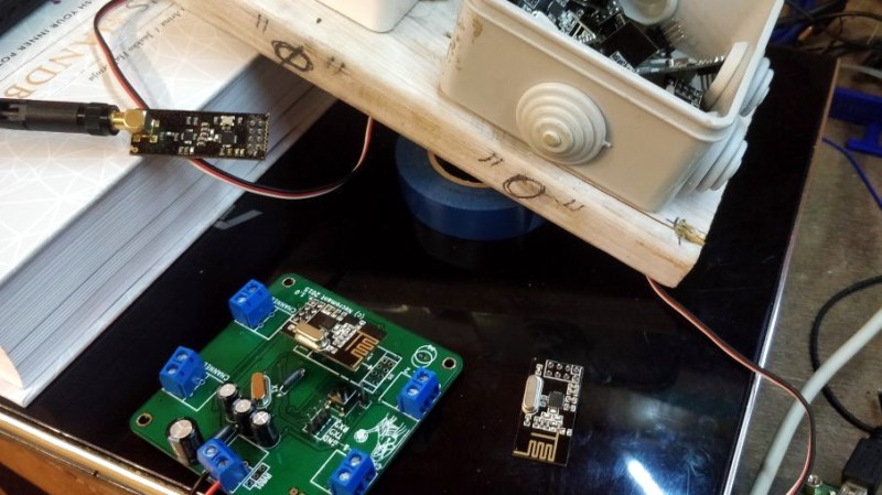
[nekromant] recently got a whole batch of units that simply refused to perform as they should, but not because they were counterfeits. The problem was that the antenna and PCB design had been “optimized” by the supplier to the point where the devices simply couldn’t work properly. Fortunately, [nekromant] leveraged an understanding of the problem into a way to fix them without going insane in the process. The test setup is shown in the image above, and the process is explained below.
This issue wasn’t new to [nekromant], as previous batches had suffered from a “magic finger problem”, where bad performance is magically solved by placing one’s finger on the antenna. This had been fixed in the past by soldering in a missing 1.0 pF capacitor, but the newest batch of nRF24L01+ units was so bad that something more needed to be done. Simply adding a 1.0 pF capacitor was no longer enough, and it’s unclear exactly why.
For reasons likely related to the PCB antenna, each radio required adding a capacitor in a value usually somewhere between 1.0 pF and 2.2 pF. But there was no way to tell which value any particular board would need. To solve this, [nekromant] made a small test rig to profile each device in turn by sending packets and measuring how many failures were recorded. After profiling each device, fixing them was a matter of informed trial-and-error. Once putting a finger on the PCB antenna begins to worsen a device’s performance rather than improve it, that module (along with whatever value of capacitor was last soldered onto it) could be dropped into the “OK” bin, and the process repeats until the pile is gone.
[nekromant] points out that the obvious lesson here is to be careful about picking suppliers, but that’s increasingly difficult to do with modules like these. An annoying manual board rework process is one thing for a small hobby project, but would be quite another issue entirely if several hundred or thousand units were involved.
Counterfeit silicon wasn’t the issue this time, but maybe brush up a little on spotting counterfeits all the same.


Just use RFM95, no need for Ghz.
One answer to that – cost.
I wonder, why no one tried to replace the PCB antenna and its matching network with balanced dipole, as recommended in datasheet? I’ve seen only an unbalanced dipole variant, where matching network is left as it is, and the length of the dipole is adjusted for best performance…
Also for some time counterfeit nRF24L01p chips worked as described in datasheet, while genuine ones had some problems. Is this still true?
What kind of range do people get with these modules?
I had to scrap an almost completed project because after doing the coding with nodes close together I discovered that they could not connect if spaced apart a couple of meters with a wall in between. Maybe I got bad units?
I think you’ve missed the part about bit rate. The faster the speed, the lower range you get. BUT: if the antenna is crap it works most terrible at 250kbps. Using a module with pa/lna for the central node gives you a very decent signal boost. Oh, and did I mention WIFI/Zigbee interference?
I think of summing all that stuff in another post later. Meanwhile thanks to HaD for featuring this small hack ;)
Best case scenario with power for module coming from LDO, no switch mode converters, and 100uF decoupling capacitor across power pins one experimenter got 12m indoors with no packets dropped, and 47m LOS range in city setting. 100m is possible in rural areas. One can more than double that by using unbalanced dipole antenna instead of that badly designed squiggle. The PA+LNA variant usually performs better, but to get to 1km of LOS range one needs to use good, noise-free power supply, decoupling and shielding…
It’s not the uF of the decoupling that matters! ESR does. Huge cap may not help, after all.
Similar here (though the project never really got off the ground) – I found that power supply ripple massively affected the link quality, but it never got to a state where I got more than 5m or so indoor with a couple of walls in the way. A BLE dev board pair was able to get coverage through the entire house, so it wasn’t purely a 2.4GHz issue.
I may revisit things to see if I can fix things by following this article (the boards superficially look the same, but that means nothing). Failing that, I was tempted by LT8900 modules.
I was able to stream ~36KB/s in the 2Mbps mode reliably at about 100 feet of open air between nodes for one project. As others have said, slowing down the radio’s data mode increases range significantly. Turning on the CRC is also important.
The clones are using a reference layout for most part except the PCB antenna. So the lack of 1uF is from there.
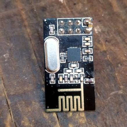
The reference design uses a literally ‘?’ shaped PCB antenna that takes up lot more space than the clones. Someone changed the type without doing the simulations and/or actual VNA measurements for the impedance.
The other common mistake is to have the antenna of these over PCB or other circuits which changes the field distribution patterns and impedance. Lots of HaD projects are guilty of ths act. This module is above on headers, so at least it is not as bad as ESP modules that are surface mounted. :P
“Hey, it works” by the DIYer is just as bad as Chinese clones.
I made a series of videos on how to design and tune these antennas.
https://youtu.be/q6f6m2j1nYs
I am curious what channel he’s running these on–I didn’t see it specified in the article but maybe it was implied by the software he’s using. I would think a good test would require you to test antenna performance at a few frequencies–at least highest and lowest. I’d like to see middle as well.
I happened to run the test on channel 76 of nrf24l01. The choice is weird, but it has the least overlaps with wifi (mine and neighbors). Since I was planning to use those only on that channel I didn’t bother checking the other channels.
Thanks for the reply. I would suggest testing on other frequencies so that you can see where the peak is. That would give you a better indication of tune quality than “does putting my finger on it make it worse”.
Regardless, good work!
@Donald Papp said: “This had been fixed in the past by soldering in a missing 1.0 pF capacitor…”
“1.0 pF capacitor” and “solder in” don’t go together well. What’s needed is a “Gimmick” capacitor.[1][2] So I’ll just leave a couple of references here, one of them being a Hack-A-Day post:
1. Gimmick Capacitor – Wikipedia
https://en.wikipedia.org/wiki/Gimmick_capacitor
2. These Capacitors Are A Cheap Gimmick
https://hackaday.com/2018/07/03/these-capacitors-are-a-cheap-gimmick/
I thought about that, but in the end you’ve got to fit those on an smd 0603 pads without tearing it away. So I picked the easy way ;)
A 1..2 pF gimmick at 2.5 GHz is physically too large and would behave like a short piece of transmission line. A tiny capacitor is needed here, not another antenna with strange dielectrical properties.
I recall reading somewhere on the data sheet that logic voltage should not exceed vdd for best RF range
Hmm. Sounds legit: current flows through protective diodes right into the vdd, rising vdd and creating ripples. That explains why caps on vdd help that much.
Except that there are no ESD diodes that are connected to the VDD directly. This is easily determned by looking at their Absolute Maximum Ratings in the datasheet.
Input voltage VI: Min -0.3 Max 5.25 V
The upper limit is not related to VDD strongly indiating that the are using a Zenzer that is connected to GND only. The diode likely rated for quite a bit higher as tolerances isn’t all that great.
As for decoupling on VDD for a part tat can draw pulses of power, duh.
Hm, nice catch. IIRC zener diodes are quite noisy. That could well be another explanation.
Sometimes you’ve got to stick it to the supplier and send the whole batch back for being unfit for purpose, that way they might learn.
Seems odd bending over backwards to fix their bad engineering.
You should tag this with NRF; there’s only like 4 stories in that tag, but it’s an easy way to find stories mentioning the Nordic modules.
nRF04L01+ typo in the tag makes this article harder to search for. Please amend so we can find in future.