One thing we love here at Hackaday is when we get to track the evolution of a project over time. Seeing a project grow over time is pretty typical — scope creep is real, after all. But watching a project shrink can be a real treat too, as early versions get refined into sleeker and more elegant solutions.
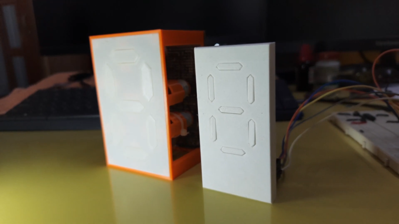
This slimmed-down mechanical seven-segment display is a perfect example of that downsizing trend. When we saw [IndoorGeek]’s first vision of an electromechanical display, it was pretty chunky. Then as now, each segment is a 3D-printed piece with a magnet attached to the rear. The segments hover over solenoid coils, which when energized repel the magnet and protrude the segment, forming the desired digit. The old version used large, hand-wound coils, though, making the display pretty bulky front to back.
Version 2 of the display takes a page from [Carl Bugeja]’s playbook and replaces the wound coils with PCB coils. We’ve seen [Carl]’s coils on both rigid substrates and flex PCBs; [IndoorGeek] used plain old FR4 here. The coils occupy four layers so they have enough oomph to extend and retract each segment, and the PCB includes space for H-bridge drivers for each segment. The PCB forms the rear cover for the display, which is also considerably slimmed down for this version. What’s the same, though, is how good this display looks, especially with strong side-lighting — the shadows cast by the extended segments are striking against the plain white face of the display.
Congratulations to [IndoorGeek] on a great-looking build and a useful improvement over the original.


Cool. Shut up and take my money!
I wonder if adding a thin foam pad between the PCB and the magnets would eliminate the clicking sound?
but the clicking sound is part of the magic!
yeah, its got to click. just like the noise those flip dot displays make. its part of the retro.
ok, next step add LEDS that are activated by contact when the segment is pushed out.
Hollow segment, LEDs in side, anode nad cathode connected to flange on edge of segment – contact is made when segment is pushed out .
Run high frequency (100ish kHz) PWM through the existing PCB coils.
Add a pick up coil for each segment and you can inductively power the LEDs.
Very creative ideas. Adding LEDs will defeat the purpose of making a mechanical display though.
Not entirely. This display provides the ability to read it by touch, so a blind person could read it. A visual+tactile display can be good for a multi-user application that needs accessibility.
If using tuned pieces of metal or wood, it could be possible to hear the number it is displaying :)
I was thinking the same thing, unless there was a single source of light and the segments were designed to reflect that light. Or reflect ambient light, maybe add retroreflective material that is somehow hidden when they are inactive.
What an incredible progression of the idea Neeraj! I love the execution on this.
I would rather move the segments inside than outside.
That way the shadows or painted edges will be contained within the segments outline, making it more readable.
I was wondering how you could set up your shadows to be consistent and this comment makes so much sense!
Really awesome project!
This is awesome but the segments don’t seem to be quite large enough. It would be cool if the segments also flipped to a black side or something but that’s just me.
google flip dot display
If I push on a segment when it is out will it cause a detectable voltage change in the coil? I was wondering because if it does you could make a “floating” numeric keypad. The pad would normally be flush with the wall, when you approach it senses you (ultrasonic sensor?) and pushes the keypad (12 keys, like a phone I guess) out, you press the keys and when you enter the right code the keys pull back, snazzy & futuristic!
Strap a couple hall sensors to the PCB, it can detect when the magnet got closer to the board. Easier than scanning the coil to see any change, and inductors are not straighforward to work with.
Execute this with a resin printer. Those gaps around the digits and plate really detract from how awesome this version is.
If you make it nearly seamless, it would be magical looking.
I’d make the little segments black, or the sides black, with a white face, so as long as you look slightly from the side, you aren’t relying on the lighting.
I am impressed, though, very good looking project. My projects look like a child made them out of macaroni.
For a similar idea how could this work laying on its back so they don’t fall back down? A rigid version so to speak.