At one point in time mechanical seven segment displays were ubiquitous, over time many places have replaced them with other types of displays. [Sebastian] has a soft spot for these old mechanically actuated displays and has built an open-source 7-segment display with some very nice features.
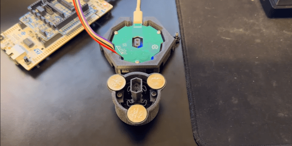
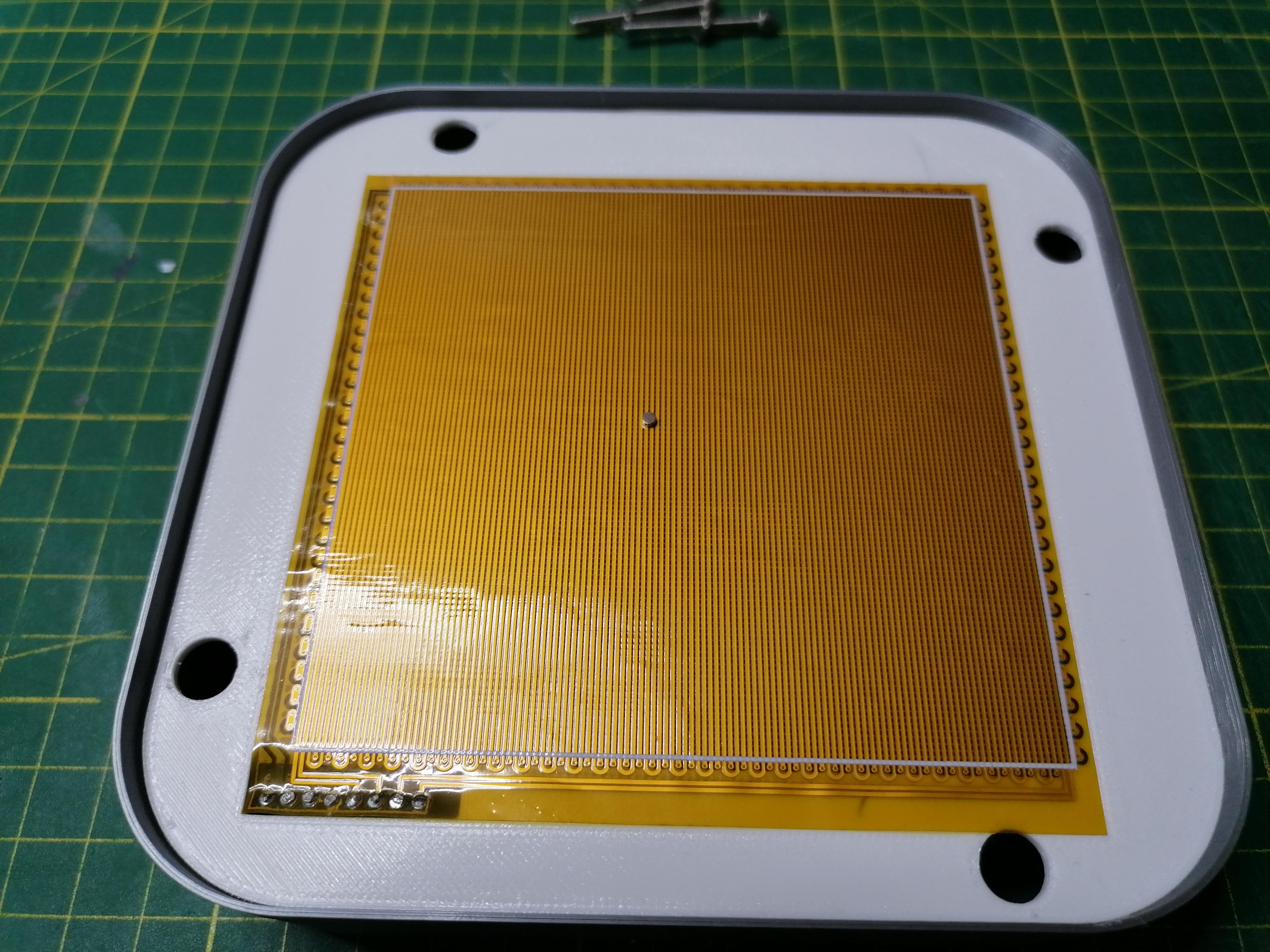
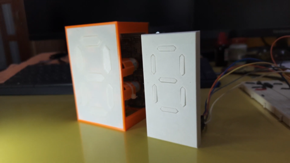
We’ve seen a good number of DIY 7-segment displays on this site before, the way [Sebastian] went about it resulted in a beautiful well thought out result. The case is 3D printed, and although there are two colors used it doesn’t require a multicolor 3d printer to make your own. The real magic in this build revolves around the custom PCB he designed. Instead of using a separate electromagnets to move each flap, the PCB has coil traces used to toggle the flaps. The smart placement of a few small screws allows the small magnets in each flap to hold the flap in that position even when the coils are off, greatly cutting down the power needed for this display. He also used a modular design where one block has the ESP32 and RTC, but for the additional blocks those components can remain unpopulated.
The work he put into this project didn’t stop at the hardware, the software also has a great number of thoughtful features. The ESP32 running the display hosts a website which allows you to configure some of the many features: the real-time clock, MQTT support, timer, custom API functions, firmware updates. The end result is a highly customizable, display that sounds awesome every time it updates. Be sure to check out the video below as well as his site to see this awesome display in action. Also check out some of the other 7-segment displays we’ve featured before.