If it weren’t for persistence of vision, that quirk of biochemically mediated vision, life would be pretty boring. No movies, no TV — nothing but reality, the beauty of nature, and live performances to keep us entertained. Sounds dreadful.
We jest, of course, but POV is behind many cool hacks, one of which is [Joe]’s neat Nipkow disk clock. If you think you’ve never heard of such a thing, you’re probably wrong; Nipkow disks, named after their 19th-century inventor Paul Gottlieb Nipkow, were the central idea behind the earliest attempts at mechanically scanned television. Nipkow disks have a series of evenly spaced, spirally arranged holes that appear to scan across a fixed area when rotated. When placed between a lens and a photosensor, a rudimentary TV camera can be made.
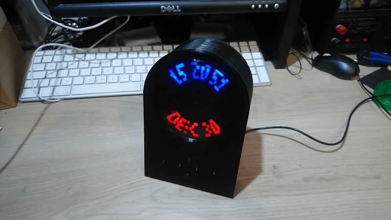
For his Nipkow clock, though, [Joe] turned the idea around and placed a light source behind the rotating disk. Controlling when and what color the LEDs in the array are illuminated relative to the position of the disk determines which pixels are illuminated. [Joe]’s clock uses two LED arrays to double the size of the display area, and a disk with rectangular apertures. The resulting pixels are somewhat keystone-shaped, but it doesn’t really distract from the look of the display. The video below shows the build process and the finished clock in action.
The key to getting the look right in a display like this is the code, and [Joe] put in a considerable effort for his software. If only the early mechanical TV tinkerers had had such help. [Jenny List] did a nice write-up on the early TV pioneers and their Nipkow disk cameras; we’ve also seen other Nipkow displays before, but [Joe]’s clock takes the concept to another level.


Will have to bookmark this one, I’ve got something a bit Nipkow-ish in the pipeline.
With a laser and some lenses, could that be a projector?
With an actual projector setup and the disk in the light path you could make a nipkow projector. Although you would need a very wide laser beam or a tiny nipkow disk.
When I imagined it in the past, I conceived of a spinning HDD platter with the holes for row spaced over 1-2 cm on towards edge of the disk (not that handy with a drill myself), with one lens to diffuse the laser to cover the spread oth the holes and another to refocus the beam the other side.
I do like the clock though!
If you have a laser with a narrow beam, mirror drums as used in the Scophony system would be the better option.
Some fans come with a built in tachometer signal, but I suppose he worked with what he had. Quite a neat project!
Oh, I also remembered that many fans have the tachometer output but are only wired for power and ground. If you check by where the wires attach, you might find a third pad for the tach.
I was thinking of doing this with an open 3.5″ hard drive. It has a synchronous motor, all the mechanics etc. Just add a micro, spindle motor drive leds/housing/defusers and drill holes in the platter.
I love the whole idea of mechanical television and Nipkow disks so this is great, but, since it is a Nipkow disk I have to ask when we get “video”?
No actual video, Sorry. Well the clock can do running text (I did not show that in the YT clip actually) so you could call that “video”.
Well considering the 32 line TV in the 20’s I guess anything that moves could be considered video.